External UDP Messages pass information from N1MM Logger+ about the contest in progress to various third-party software programs. UDP Messages can be sent to remote addresses, provided the receiving computer can be reached through its local router. You cannot send broadcasts (like xx.xx.xx.255) to remote subnets.
There are additional UDP Messages built into N1MM Logger+ which support various program operation and interaction features (networking for multi-computer stations or rotor control), but (except as noted below) they are not very useful for general users.
Vasily K3IT has found that if both SO_BROADCAST and SO_REUSEADDR options are used when a UDP port is opened, it is opened in a ‘non-exclusive’ mode. This allows multiple applications to share the same port, as long as they all follow this method. Using these flags helps avoid port conflict issues.
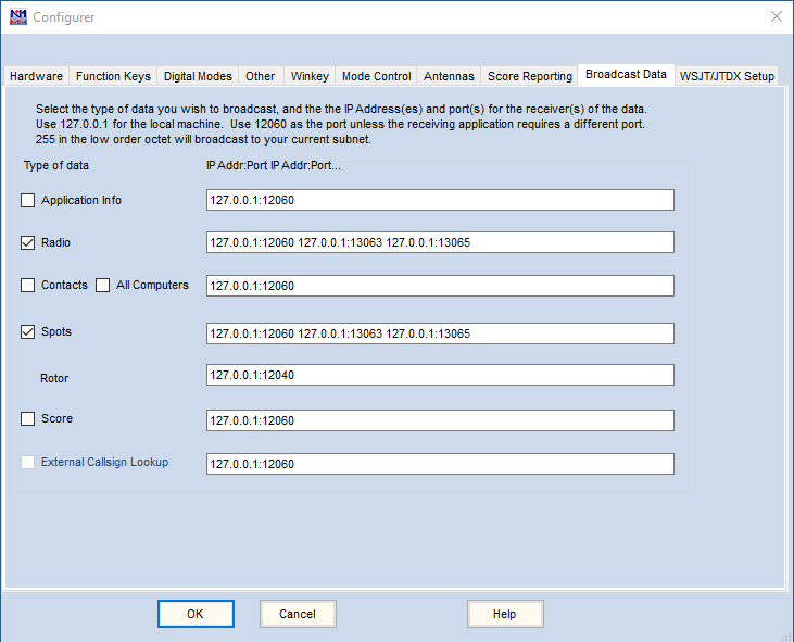
To enable external UDP Messages select >Config >Config Ports… >Broadcast Data.
Selecting which UDP Messages to Send
| Checkbox | Explanation |
| Application Info | Sends information about the station and the current contest (station name, contest database, contest name…) when the program launches, when a new contest is opened, or when a different contest or contest instance is selected in the Contest Dialog window. See full field list below |
| Radio | Sends radio information (mode, frequency, antenna, operator…) at least every 10 seconds or when radio frequency or mode change. See full field list below |
| Contacts | Sends contact information (time, callsign, mode, frequency, exchange…) when a new contact (QSO) is added to the log, when an existing contact is edited in the log, or when an existing contact is deleted from the log. See full field list below |
| All Computers | Sends all contact info from all stations on a network from this station. This command is useful only in Networked Computer mode. When enabled (together with Contact) at any station, that station will resend every contact that it receives to the UDP port specified. The XML format is the same as for Contact except that IsOriginal will be set false. CAUTION: Multiple, misconfigured stations with All QSOs enabled could result in a circular network storm of contact packets |
| Spots | Sends info about spots as they are processed (added or deleted). Spots may originate from telnet (including RBN), from logging QSOs, or from local spots stored in the Bandmap |
| Score | Can be used for score reporting within the local network. To report scores to online score reporting databases, use the Score Reporting tab in the Configurer |
| External Callsign Lookup | Used to send LookupInfo packets to a third party application such as a general-purpose logging program prior to completing the contact. See the description of the LookupInfo packets below |
Setting the Destination IP Addresses
The Application, Radio, and Contact packets will be addressed to destinations indicated in this dialog window. To send them to a program running on this PC, use the address 127.0.0.1. To send them to another PC on this subnet, enter its IP on the corresponding line. To send them to all PCs on this subnet, enter 255 as the last number (octet) of this subnet’s address. For example: if PCs on this subnet have the address 192.168.1.n, use 192.168.1.255 to send the packets to all of the PCs on this network. Separate multiple destination IP address from each other with a space. Do not specify 255 in the higher order octets, or you will risk broadcasting to the internet. While eventually the packets will be discarded by internet routers, this will not endear you to your ISP.
Setting the Destination IP Port Numbers
Except as noted below. the recommended default port number for N1MM Logger applications is 12060. Destination port numbers are defined by adding a colon “:” to the IP address, followed by the port number. For example, to send packets to port 12060 on this PC and to all other PCs on this subnet: 127.0.0.1:12060 192.168.1.255:12060
Other UDP Message Settings
Optional External Message statements allow different external message types to be sent to different IP addresses, multiple IP addresses, and multiple port numbers. Refer to the instructions for those applications for confuguration details about adding their packet addressing information to the N1MM Logger.INI file.
Formatted XML text of the following packets is available in the Downloads section of the website under Additional Support Files.
XML Schema and Message Field Lists
Application Info
<?xml version="1.0" encoding="utf-8"?>
<AppInfo>
	<app>N1MM</app>
	<dbname>N8SL_FIELDDAY.s3db</dbname>
	<contestnr>2</contestnr>
	<contestname>ARRL-FIELD-DAY</contestname>
	<StationName>80M-TENT</StationName>
	<mycall>N8SL</mycall>
</AppInfo>
NOTE: contestnr is a unique number assigned to this contest instance in this database. Do not expect the same contestnr to be assigned to another computer running the same contest name.
Contact
Contact Info UDP packet
<?xml version="1.0" encoding="utf-8"?>
<contactinfo>
	<app>N1MM</app>
	<contestname>CWOPS</contestname>
	<contestnr>73</contestnr>
	<timestamp>2020-01-17 16:43:38</timestamp>
	<mycall>W2XYZ</mycall>
	<band>3.5</band>
	<rxfreq>352519</rxfreq>
	<txfreq>352519</txfreq>
	<operator></operator>
	<mode>CW</mode>
	<call>W1AW</call>
	<countryprefix>K</countryprefix>
	<wpxprefix>W1</wpxprefix>
	<stationprefix>W2XYZ</stationprefix>
	<continent>NA</continent>
	<snt>599</snt>
	<sntnr>5</sntnr>
	<rcv>599</rcv>
	<rcvnr>0</rcvnr>
	<gridsquare></gridsquare>
	<exchangel></exchangel>
	<section></section>
	<comment></comment>
	<qth></qth>
	<name></name>
	<power></power>
	<misctext></misctext>
	<zone>0</zone>
	<prec></prec>
	<ck>0</ck>
	<ismultiplierl>1</ismultiplierl>
	<ismultiplier2>0</ismultiplier2>
	<ismultiplier3>0</ismultiplier3>
	<points>1</points>
	<radionr>1</radionr>
    <run1run2>1<run1run2>
	<RoverLocation></RoverLocation>
	<RadioInterfaced>1</RadioInterfaced>
	<NetworkedCompNr>0</NetworkedCompNr>
	<IsOriginal>False</IsOriginal>
	<NetBiosName></NetBiosName>
	<IsRunQSO>0</IsRunQSO>
	<StationName>CONTEST-PC</StationName>
	<ID>f9ffac4fcd3e479ca86e137df1338531</ID>
	<IsClaimedQso>1</IsClaimedQso>
    <oldtimestamp>2020-01-17 16:43:38</oldtimestamp>
    <oldcall>W1AW</oldcall>
    <SentExchange>XYZ NY</SentExchange>
</contactinfo>
NOTES
- IsOriginal indicates that this is the station on which this contact was initially logged – to differentiate it from another station that may be forwarding the contact record. StationName is the netbios name of the station that sent this packet, not necessarily the name of the station that logged this contact.
- ”power”, “name” and “qth” refer to information about the station being worked in this contact. In a contest where transmit power is part of the exchange, “power” will contain the received power exchange from the other station.
- “run1run2” refer to the run radio number is a multi-2 arrangement.
- “band” is composed of 2 or 3 characters that may include localized delimiters. For example, 80 meters may be “3.5” or “3,5”; 160 meters as “1.8” or “1,8” The user’s Windows setting will determine which delimiter is present in the band tag
- ID is a 32 byte unique GUID identifier for each contact in the log. Note that it is sent as 2 hex characters per byte.
- IsClaimedQso will default initially to “1” for all contacts and is set to “0” when a contact is declared to be an X-QSO
- oldtimestamp and oldcall are used in contactreplace packets to indicate the time and callsign that were originally logged before editing, in case either was changed. In contactinfo packets they are the same as timestamp and call respectively
- SentExchange is the contents of the Sent Exchange box in the contest setup dialog window. This is not necessarily the same as the actual exchange sent during the QSO; there is no signal report, the serial number (# or 001) is a placeholder for the actual serial number (sntnr), and there is no guarantee that what is in the Sent Exchange box is the same as what was in the function key message
- ADIF fields in ContactInfo – It may be tempting to assume that there is a one-to-one correspondence between fields in the contactinfo messages and similar fields in the ADIF specification, but this is not always the case. The best example is the Section field in the contactinfo message; this means whatever the rules for the particular contest define it to mean. In a very few contests, the Section field is the same as the ADIF ARRL_SECT; in some other contests and for most geographical locations, it may be the same as STATE in ADIF. However, in some contests for some geographical locations (e.g. Alaska, Hawaii, the District of Columbia, the Canadian Atlantic provinces, Canadian northern territories) the section identifier specified in the contest rules might not match either ADIF field. Another example is the Zone field, which often means the same as CQZ in ADIF, but in some contests it means the same as ITUZ. Yet another example is the frequency field, which is not in the same format as in ADIF; in the contact info and radio info message, the frequency is exported in units of 10 Hz.
Contact Replace
The Contact Replace packet contains the same fields as Contact Info above, but with <contactreplace > XML tags.
<?xml version="1.0" encoding="utf-8"?>
<contactreplace>
	<app>N1MM</app>
	<contestname>CWOPS</contestname>
	<contestnr>73</contestnr>
	<timestamp>2020-01-17 16 :43:38</timestamp>
	<mycall>W2XYZ</mycall>
	.
	.
	.
</contactreplace>
When a user edits an existing contact record, the program will send a pair of UDP packets: A < contactdelete > packet, followed by a < contactreplace > packet. The < contactdelete > packet will contain the existing record’s callsign and timestamp, in the event that the < contactreplace > packet includes a new timestamp or callsign for this record. (The need for this has now been eliminated with the addition of the oldcall and oldtimestamp fields.)
Contact Delete
<?xml version="1.0" encoding="utf-8"?>
<contactdelete>
	<app>N1MM</app>
	<timestamp>2020-01-17 16 :43:38</timestamp>
	<mycall>W2XYZ</mycall>
	<band>3.5</band>
	<call>W1AW</call>
	<contestnr>73</contestnr>
	<StationName>CONTEST-PC</StationName>
	<ID>a1b2c3d4e5f6g7h</ID>
</contactdelete>
LookupInfo
<?xml version="1.0" encoding="utf-8"?>
<lookupinfo>
	<app>N1MM</app>
	<contestname>CWOPS</contestname>
	<contestnr>73</contestnr>
	<timestamp>2020-01-17 16 :43:38</timestamp>
	<mycall>W2XYZ</mycall>
	.
	.
	.
</lookupinfo>
NOTE: The LookupInfo UDP packet structure is identical to the ContactInfo packet described previously. The purpose of the LookUp packet is to advise a third-party application (usually a general purpose logging program) of the intention to work a station. The difference between the two packets is the timing of their transmission. The LookupInfo packet is sent after entering a callsign in the Entry Window and pressing the [spacebar], but before the callsign is logged in the N1MM database. In contrast, the ContactInfo packet is sent after a new record has been added to a contest log. LookupInfo and ContactInfo are two separate functions and each needs to be configured in N1MM+’s Configurer >Broadcast Data tab. The suggested default port for LookupInfo packets is 12060.
Radio Info
<?xml version="1.0" encoding="utf-8"?>
<RadioInfo>
	<app>N1MM</app>
	<StationName>CW-80m</StationName>
	<RadioNr>1</RadioNr>
	<Freq>352211</Freq>
	<TXFreq>352211</TXFreq>
	<Mode>CW</Mode>
	<mycall>W1ABC</mycall>
	<OpCall>W1ABC</OpCall>
	<IsRunning>False</IsRunning>
	<FocusEntry>204626</FocusEntry>
	<EntryWindowHwnd>275678</EntryWindowHwnd>
	<Antenna>8</Antenna>
	<Rotors></Rotors>
	<FocusRadioNr>1</FocusRadioNr>
	<IsStereo>False</IsStereo>
	<IsSplit>False</IsSplit>
	<ActiveRadioNr>1</ActiveRadioNr>
	<IsTransmitting>False</IsTransmitting>
	<FunctionKeyCaption></FunctionKeyCaption>
	<RadioName></RadioName>
    <AuxAntSelected>-1</AuxAntSelected>
    <AuxAntSelectedName></AuxAntSelectedName>
    <IsConnected></IsConnected>
</RadioInfo>
Radio Info Notes:
- app is a short name of the logger program sending the packet. Examples: “N1MM”, “DXLab”, “Logger32”, “UcxLog”, “Log4OM”
- StationName is the NetBios name of the computer that is sending these messages. It is the name used in Multi-Computer networking. Windows limits it to 15 characters. If the computer name is greater than 15 characters long, the first 15 characters will be used.
- RadioNr is the radio number associated with a specific XML packet – in other words, the source of the information in that packet. When in SO2V or SO2R mode, N1MM+ sends two packets every ten seconds – one packet each from RadioNr1 and RadioNr2
- Freq is the receive frequency represented as values to the tens digit with no delimiter. For example: 160 meters: 181234; 40 meters: 712345; 10 meters: 2812345; 6 meters: 5012345
- TXFreq is the transmit frequency represented as values to the tens digit with no delimiter. For example: 160 meters: 181234; 40 meters: 712345; 10 meters: 2812345; 6 meters: 5012345
- Mode is the logging mode and could be any one of the following: CW, USB, LSB, RTTY, PSK31, PSK63, PSK125, PSK250, QPSK31, QPSK63, QPSK125, QPSK250, FSK, GMSK, DOMINO, HELL, FMHELL, HELL80, MT63, THOR, THRB, THRBX, OLIVIA, MFSK8, MFSK16
- mycall is the station callsign
- OpCall is the callsign entered by the operator after OPON (or Ctl-O). Defaults to the station call
- IsRunning represents the value of the RUN versus S&P radio buttons in the Entry Window. If you are on your CQ frequency, IsRunning will normally be True
- FocusEntry is the Windows assigned handle of the Entry Window with program focus
- EntryWindowHwnd allows external software to send commands to a specific EntryWindow (i.e. using AHK to send F1 to EW2 etc.)
- Antenna is the currently selected antenna for this radio (0-63), from the Antenna tab in the Configurer
- Rotors is the name of the currently selected rotor from the Antenna table in the Configurer
- FocusRadioNr Receive Radio Focus or keyboard focus – the Green Dot in the Entry Window. Enables signal switching for SO2R operation, facilitating the routing of Microphone, Audio, PTT, CW signals to/from the selected radio. FocusRadioNr toggles between 1 and 2 when the program, a mouse click, or the \ key selects the opposite Entry Window
- IsStereo enables audio switching for SO2R operation.The ` key (backquote) toggles its value between True and False
- ActiveRadioNr Transmit Radio Focus – the Red Dot in the Entry Window. Enables signal switching for SO2R operation, facilitating the routing of Microphone, Audio, PTT, CW signals to/from the selected radio. ActiveRadioNr toggles between 1 and 2 when the program or pressing the [Pause] key selects the opposite Entry Window
- IsSplit Transceiver is in Split VFO mode (for example: vfoA=Rx, vfoB=Tx). Not available on all – especially older – rigs
- IsTransmitting The program (as distinct from the radio) is in transmit (True) or receive (False) mode. See IsTransmitting warning, below
- FunctionKeyCaption The label of the Function Key that was pressed to initiate this transmission
- RadioName The name of the radio, as shown in the Entry Window (i.e. “TS-590”)
- AuxAntSelected is normally “-1”, until the user presses an Entry Window function key containing the {auxantsel} macro. A UDP packet containing the selected antenna number is sent once per keypress, after which <AuxAntSelected> reverts to “-1”
- AuxAntSelectedName is normally blank, until the user presses an Entry Window function key containing the {auxantsel} macro. A UDP packet containing the selected antenna name is sent once per keypress, after which <AuxAntSelectedName> reverts to a blank field
- IsConnected indicates whether a radio is connected. It may take some time for a disconnection (False) to be registered
The program sends Radio Info packets at 10 second intervals, or immediately after an event where any of the information in one of these fields changes (for example: user changes bands, spins the VFO dial, switches from Run to S&P, or selects vfoB).
The IsTransmitting tag in RadioInfo only displays as True when N1MM+ has initiated a transmission. When a transmission is initiated external to N1MM+ – for example, a microphone PTT button or CW paddle key – IsTransmitting will still be displayed as False. Be careful when using IsTransmitting to control external devices that need to know when the radio is in Tx or Rx.
Using RadioInfo broadcasts when the Logger is in SO2V mode may require special consideration. In SO2V, packets in which RadioNr and ActiveRadioNr are different from each other should not be relied upon for information about the transmit frequency.
Explanation: N1MM+ treats the two VFOs in SO2V similarly to the way it treats the two radios in SO2R. Broadcasts with RadioNr = 1 relate to VFO A (the main receiver in most dual-receiver radios), and broadcasts with RadioNr = 2 relate to VFO B (the subreceiver in radios so equipped). In each of these broadcasts, the exported value of TxFreq is normally the same as the receive frequency (Freq), regardless of which VFO is active (as if RadioNr 1 and RadioNr 2 were two separate radios). The exception is the special case when the program is in Split mode. In this case (and only in this case) TxFreq will indicate the frequency in the other VFO to reflect the Split mode status.
What this means is that programs receiving RadioInfo broadcast packets and requiring knowledge of the transmit frequency or band (such as programs controlling amplifiers or antenna switches) must take the ActiveRadioNr into account. In SO2V mode, the TxFreq reported in packets in which RadioNr is not the same as ActiveRadioNr will generally not be the actual transmit frequency. This is not likely to be a major problem when the two VFOs are on the same band, but if the two VFOs are on different bands, the TxFreq reported in these inactive radio packets will be misleading. To determine the correct transmit frequency, when N1MM+ is in SO2V such programs should only use TxFreq from packets in which RadioNr and ActiveRadioNr have the same value.
Rotator Control
Messages to operate the separate Rotator Control program are sent automatically when the user selects >Tools >Turn Rotor (alt+J), and do not require configuration settings or modifications to the N1MM Logger.ini file. The messages are always sent on port 12040. See the Rotator Control chapter for more information.
Spot Data
Spot UDP Packet:
<?xml version="1.0" encoding="utf-8"?>
<spot>
	<app>N1MM</app>
	<StationName>CONTEST-PC</StationName>
	<dxcall>AL3CDE</dxcall>
	<frequency>7061.2</frequency>
	<spottercall>K2PO/7-#</spottercall>
	<timestamp>2O20-Ol-l7 17:19:37</timestamp>
	<action>add</action>
	<mode>CW</mode>
	<comment>CW 9 DB 18 WPM CQ AK </comment>
	<status>single mult</status>
	<statuslist>single mult</statuslist>
</spot>
- StationName – the callsign shown in the station dialog
- dxcall – the station that is spotted
- spottercall – the station that spotted the call (StationName for stations worked, or spotted locally)
- comment – the comment from the spot
- action – whether this spot was added (“add”) or deleted (“delete”). Spots are deleted when the spotted station moves within a band
- status – dupe, mult etc. See below for values
- timestamp – the time of the spot
The values for status are:
- busy – marked by N1MM user as a frequency to note (e.g. a local spot made using the “Mark” button in the Entry window)
- bust – a busted call (when CT1BOH tags are present)
- cq – the cq frequency on this band (last place F1 was pressed)
- dupe – duplicate contact (includes contacts that are not workable for points in this contest)
- qtc – a WAE qtc
- single mult – this spot is a single multiplier in this contest
- double mult – this spot is a double (or more) mult in this contest
- new qso – this spot is for a station that would be a new contact in this contest but is not a multiplier
Score Reporting
Navigate to the Configurer >Config >Configure ports… >Score Reporting tab to send contact info to the online score reporting websites.
<?xml version="1.0"?>
<dynamicresults>
	<contest>ARRL-FIELD-DAY</contest>
	<call>K8UT</call>
	<ops>VA5DX</ops>
	<class power="HIGH" assisted = "ASSISTED" transmitter="UNLIMITED"
		ops="MULTI-OP" bands="ALL" mode="MIXED" overlay="N/A">
	</class>
	<club></club>
	<qth>
		<dxcccountry>K</dxcccountry>
		<cqzone>4</cqzone>
		<iaruzone>8</iaruzone>
		<arrlsection>MI</arrlsection>
		<stprvoth>MI</stprvoth>
		<grid6>EN82BK</grid6>
	</qth>
	<breakdown>
		<qso band="20" mode="CW">156</qso>
		<point band="20" mode="CW">312</point>
		<qso band="20" mode="ALL">15</qso>
		<point band="20" mode="ALL">30</point>
		<qso band="20" mode="PH">385</qso>
		<point band="20" mode="PH">384</point>
		<qso band="15" mode="CW">19</qso>
		<point band="15" mode="CW">38</point>
		<qso band="15" mode="ALL">14</qso>
		<point band="15" mode="ALL">28</point>
		<qso band="15" mode="PH">30</qso>
		<point band="15" mode="PH">30</point>
		<qso band="10" mode="CW">6</qso>
		<point band="10" mode="CW">12</point>
		<qso band="10" mode="ALL">3</qso>
		<point band="10" mode="ALL">6</point>
		<qso band="80" mode="CW">24</qso>
		<point band="80" mode="CW">48</point>
		<qso band="80" mode="ALL">75</qso>
		<point band="80" mode="ALL">150</point>
		<qso band="80" mode="PH">136</qso>
		<point band="80" mode="PH">136</point>
		<qso band="0.7" mode="PH">l</qso>
		<point band="0.7" mode="PH">2</point>
		<qso band="6" mode="CW">l</qso>
		<point band="6" mode="CW">2</point>
		<qso band="6" mode="ALL">54</qso>
		<point band="6" mode="ALL">108</point>
		<qso band="6" mode="PH">9</qso>
		<point band="6" mode="PH">9</point>
		<qso band="40" mode="CW">625</qso>
		<point band="40" mode="CW">1250</point>
		<qso band="40" mode="ALL">2</qso>
		<point band="40" mode="ALL">4</point>
		<qso band="40" mode="PH">746</qso>
		<point band="40" mode="PH">746</point>
		<qso band="total" mode="ALL">2301</qso>
		<point band="total" mode="ALL">3295</point>
	</breakdown>
	<score>3295</score>
	<timestamp>2020-01-17 17:33:37</timestamp>
</dynamicresults>
Sending Spectrum Data to N1MM+
N1MM+ receives spectrum data from SDR receivers on port 13064. Follow this XML layout:
<?xml version="1.0" encoding="utf-8"?>
<Spectrum>
	<app>WaterfallBandmap</app>
	<Name>NlMM SDR1</Name>
	<LowScopeFrequency>14000</LowScopeFrequency>
	<HighScopeFrequency>14055</HighScopeFrequency>
	<ScalingFactor>0.3125</ScalingFactor>
	<DataCount>475</DataCount>
	<SpectrumData>0,0,0,1,0,0,0,0,1,0,0,0,0,0,0,0,0,1,0,0,0,0,0,0,0,0,0,0,0,0,1,0,0,0,1,0,0,0,1,0,0,0,0,0,0,0,0,0,0,0,0,1,0,0,0,1,0,0,0,0,0,
	0,0,0,0,0,0,0,0,0,0,0,0,0,0,0,1,0,0,1,0,0,0,0,1,0,0,0,0,0,0,0,0,0,1,0,0,0,0,0,0,0,0,0,0,0,0,0,0,0,0,0,0,0,0,4,0,0,0,0,1,0,0,1,0,0,0,0,0,0,0, 0,0,0,0,1,0,0,0,0,0,0,0,0,0,0,0,0,0,0,1,1,1,0,0,0,0,0,0,0,0,19,25,0,0,0,0,0,0,0,4,8,0,0,0,0,0,0,0,0,0,0,0,0,0,0,0,1,0,0,0,0,0,0,0,0,0,0,0,0, 1,0,0,0,0,0,0,1,0,0,0,0,0,0,0,0,1,0,0,1,0,0,0,0,0,0,0,0,0,1,0,0,0,0,0,0,0,0,0,1,0,0,0,0,0,0,0,0,0,0,0,0,0,0,0,0,0,0,0,0,0,1,0,0,0,1,0,0,0,0, 0,0,0,0,0,0,0,0,0,0,0,0,0,0,0,0,15,0,0,0,0,0,38,50,32,0,0,0,0,0,0,0,0,0,0,0,0,0,0,0,0,0,0,0,0,1,1,0,0,0,0,0,0,0,0,0,0,0,0,0,0,0,0,0,0,1,1,0, 0,0,0,1,0,0,1,0,0,0,0,0,0,0,0,0,0,0,0,0,0,0,0,0,0,0,0,0,0,0,0,0,0,0,0,0,0,0,0,0,0,0,0,0,0,0,0,0,0,0,0,0,0,1,0,0,0,0,0,0,0,0,0,0,0,0,0,0,0,0,0, 0,0,0,0,0,0,0,0,0,0,0,0,0,0,0,1,0,0,0,0,1,0,0,0,0,0,0,0,0,0,0,0,0,0,0,0,0,0,0,0,0,0,1,0,0,0,0,0,1,0,0,0,0,0,0,1,0,0,0,1,0,0,0,0,0,0
	</SpectrumData>
</Spectrum>
Notes:
- Name is the name of your source. It will be shown in the N1MMPlus UI
- LowScopeFrequency is lowest frequency represented by the signal levels in SpectrumData
- HighScopeFrequency is highest frequency represented by the signal levels in SpectrumData
- ScalingFactor is a number that converts your 0-N data in SpectrumData to dB for display in the UI
- DataCount is the number of signal levels sent in SpectrumData
- SpectrumData is comma separated signal level values. Icom uses a range from 0-160. We can accept integer values from 0-65535.
- Spectrum Window help can be found at: Spectrum Window Help
To show this data in N1MM+:
- Open a Spectrum Display window (Windows/Spectrum Display).
- Right-click and change Spectrum Source to “Source Name”.
- Set the source name to the Name you are sending in the message above.
We’ve tried to minimize the development effort from your side by only requiring six pieces of metadata and your level information in the same fashion that you display level data on your UI. Icom provides this data about 3x per second and that seems adequate. We wouldn’t want more than 5x to 10x per second to avoid overloading the users machines, since so many users have older processors.
In addition to the xml data, you would need to allow your users to specify an IP address to send the data to. You will probably want to allow your users to name the source, in the event there is more than one spectrum display on their networks.
If you would like to see what the spectrum UI looks like, I have prepared a 4 minute video at: Spectrum Video
Setting N1MM’s Frequency from an External Program
You can send a QSY command to N1MM (and therefore your connected radio) using the Radio_SetFrequency packet. The packet encoding must use UTF8, and the port set for 13064. Note that mouse button <Left>=Radio 1, and when running SO2V/R <Right>=Radio 2.
<?xml version="1.0" encoding="utf-8"?>
<radio_setfrequency>
	<app>WaterfallBandmap</app>
	<radionr>1</radionr>
	<frequency>14053.284</frequency>
	<mousebutton>Left</mousebutton>
</radio_setfrequency>
You will encounter port errors when two programs – like N1MM+ and WSJT-X – try to access the same com ports in Windows. The solution requires some form of serial port sharing. You have many choices: VSPE, com0com, LP-Bridge, Win4K3… We do not plan to be prescriptive – use whichever one you can get to work or is included with your general logging program.
OR
If you are going to be running a dedicated JT65 / FT8 operation with WSJT-X and are just using N1MM+ as a back-end contest database, you can create a custom INI file that launches N1MM+ without enabling its CAT interface. This prevents any of the serial port complications. See the documentation about using a custom INI file and launching N1MM+ with custom INI settings enabled here, in the section called Multiple ini files.
Frankly, though, if at all possible it would probably be better to use the integration between WSJT-X and N1MM+ described here (in the description of the WSJT Decode List window). This method in effect allows both programs to share rig control by having WSJT-X do its rig control by sending commands to N1MM+ instead of directly to the radio. This method does not use UDP port 2333; instead, it communicates with WSJT-X using the protocol defined in WSJT-X (and not described here) on port 2237.