Digital Modes
WSJT (FT8,FT4) versus other digital modes (RTTY, PSK)
There are two broad classes of digital modes supported by N1MM+.
The first class of digital modes comprises “conversational” keyboard-to-keyboard modes in which the two parties to a QSO exchange messages made up of characters (letters, numbers or punctuation characters). These messages may be of arbitrary lengths and may contain any information that can be written down in letters and numbers. There is no restriction on when a transmission may begin, other than the usual admonition to avoid having both parties to a QSO transmitting at once. These modes are conceptually quite similar to CW. N1MM+ implements them with the help of either a hardware interface (TNC or TU) or more often, using “digital engine” software. This software, in conjunction with a sound card or codec, acts as a modem to translate when transmitting between characters, either stored in message files or input from the keyboard, and the varying frequencies that are actually transmitted, and on receive, between the received signals and the characters displayed on the screen. The digital engine software may also display some kind of tuning aid to help users to tune signals in accurately.
The second class of digital modes is a family of modes supported by the WSJT-X program and its offshoots. The best-known of these modes are FT8 and FT4, but there are many more. All of these modes share similar characteristics. They are all synchronized to clock time, to within a tolerance of around 1 second; all of the FT8 signals being transmitted at any time are in lock-step. All transmitted messages in a given mode are exactly the same length. The contents of the messages are very limited; there are only half a dozen stereotyped message formats, and the contents must fall within narrowly-defined categories. The full range of contest exchanges seen in CW, SSB and RTTY contests cannot be supported by WSJT-X and similar programs. Only a few contest exchange types are supported: North American and European VHF contest exchanges, the ARRL RTTY Roundup exchange, and the ARRL Field Day Exchange are the only contest exchanges supported.
This raises the question of why anyone would want to use these modes in contests, given the restrictions described in the previous paragraph. The answer is that these modes are able to support communications under conditions where traditional modes fail. The name “WSJT” stands for “Weak Signal Joe Taylor” (Joe Taylor, K1JT, is the inventor of these modes), and as the “Weak Signal” part of that name suggests, it is possible for stations with modest power and antennas to communicate using these modes when traditional modes fail. The FT8 mode in particular became widely popular for DXing, and demands for the ability to use it in contests followed, particularly for popular VHF contests and Field Day.
Because of the differences in the way these modes work and are implemented, the interaction between N1MM+ and the WSJT-X digital engine is different from the interaction with digital engines for the other digital modes. The entire conduct of QSOs in WSJT modes is controlled by the WSJT-X program. The only role that N1MM+ plays is to perform radio control functions on behalf of WSJT-X, and to store logged QSOs in a combined log that includes contacts made in other modes, including CW and SSB as well as the WSJT-mode contacts. By using N1MM+ in combination with WSJT-X, users are able to combine contacts made in all modes into a single log for dupe- and multiplier-checking.
The interaction between N1MM+ and WSJT-X is controlled through a special window in N1MM+ called the WSJT Decode List window. Instructions on how to interface the two programs and use them in combination in contests is found in the manual chapter on the WSJT Decode List Window.
The rest of this chapter deals only with traditional conversational digital modes (RTTY, PSK and similar digital modes).
General RTTY and PSK Information
Digital mode contesting is growing rapidly. N1MM Logger+ supports digital mode contesting, not only RTTY but also other digital modes including the modes implemented in WSJT-X and similar programs. If you are new to digital modes, you might want to read over this section. If you are familiar with digital modes and eager to get N1MM Logger+ working for them, you might want to proceed directly to the Digital Setup section for keyboard-to-keyboard modes like RTTY and PSK, or to the Decode List Window chapter for WSJT modes like FT8 and FT4.
RTTY Information
This section contains some general information about operating in RTTY that is not directly related to N1MM Logger+. For RTTY newbies, it is recommended that you read AA5AU’s tutorial on getting started on RTTY. If you are new to digital mode contesting in general and RTTY in particular, the following information may also be helpful. If you are an old-timer on RTTY, you can probably skip this section.
Before the spread of personal computers, RTTY was the most prevalent digital mode (other than CW, that is), and was done using surplus teletype equipment – mechanical teleprinters. This equipment posed severe constraints on the RTTY mode that are still evident today. Despite these constraints, RTTY has proven to be quite well-adapted to contesting, and it is still by far the most common digital contesting mode.
More recently, these mechanical teleprinters have been replaced by other devices. At first these were mostly separate boxes containing embedded microprocessors (called “terminal units”. “TUs” or “TNCs”), but now the most common device for decoding and encoding RTTY is simply a sound card in a personal computer. N1MM Logger+ is capable of using either a hardware terminal unit or one of several software “engines”, including MMTTY, MMVARI, Fldigi and 2Tone. Because there is no one method, whether it be a software program or a hardware modem, that performs better than the others under all conditions, N1MM Logger+ also supports the capability to run two or more such methods in parallel, thus gaining the advantages of both. For example, a user might choose to use a terminal unit such as the HAL DXP-38 in parallel with one or more copies of MMTTY using different decoding algorithms and parameters, in the hope that when conditions are marginal, one or another of the parallel decoders will succeed even when the others are failing to decode accurately.
The most commonly used digital engine for RTTY is MMTTY. MMTTY performs very well, and offers a wide range of adjustments and options that are not available with the other available choices. However, MMTTY does not support other digital modes like PSK31. Amateurs who wish to use other digital modes will have to use either MMVARI or Fldigi as the digital engine for those modes, and users who are accustomed to using one of these engines for other modes may prefer to use the same engine for RTTY instead of switching to MMTTY. MMVARI comes pre-loaded with N1MM Logger+, whereas MMTTY, Fldigi and 2Tone must be downloaded and installed separately.
An RTTY signal is a single carrier (like CW), but instead of being modulated on and off like CW, the transmitted power is kept constant, and modulation is imposed by changing the frequency by a preset amount; in amateur usage, the historical practice is to use a “shift” of 170 Hz. That is, RTTY is modulated using frequency-shift keying (FSK). The frequency shifting can be done either within the radio in radios which support this method, or external to the radio at audio frequencies (for example, in a computer sound card).
The first method (usually called FSK) requires an on-off keying signal to be applied to a keying input to the radio. This keying is very similar to CW keying, except that instead of turning the carrier on and off as in CW, closing the key input shifts the transmitter’s frequency. FSK therefore requires an on-off keying interface between the computer and the radio, and the radio must have the internal circuitry required to perform the frequency shifting. Radios that support this FSK mode usually have other features that assist RTTY operators, such as specialized filtering.
The second method, using audio tones fed into an SSB transmitter which converts the tones to RF in exactly the same way that SSB converts audio voice frequencies to RF, is called Audio Frequency Shift Keying (AFSK). AFSK can be used with any SSB transmitter. Because the optimum filtering and other settings for RTTY operation are different from those for voice communication, some transceivers offer special AFSK or digital-mode modes, but fundamentally these specialized audio digital modes operate in the same way as SSB.
There are never-ending arguments among amateurs as to which method is better, FSK or AFSK. If a station has been successfully set up for other sound-card digital modes, such as PSK31, that same setup can be used for AFSK RTTY, whereas the hardware configuration needed for FSK is unique to RTTY and cannot be used for other digital modes. However, some radios do not support the use of narrow receiving filters in SSB mode, which makes FSK better for RTTY contesting with those radios from an operational point of view. From a signal quality point of view, the very best AFSK setups can produce signals that are somewhat cleaner (occupy less spectrum) than most FSK transmitters are capable of, but on the other hand, a poorly set up AFSK station can transmit spurious signals, splatter or hum and noise. Badly configured AFSK setups are unfortunately more common than they should be, and give AFSK a bad name. When using AFSK, care must be taken to ensure that audio levels are set correctly; FSK does not require the same level of care.
Whether using FSK or AFSK, digital modes are harder on transmitting equipment than CW and SSB because of the higher duty cycle (sustained periods of full-power transmitting). As a result, it is important not to overstress the transmitter. It is also important to take steps to avoid transmitting extraneous noises or spurious signals, and to ensure that neither audio harmonics nor intermodulation distortion (IMD) products are generated anywhere in the signal chain.
Here are some tips for RTTY setup and operation:
Hardware interfacing:
- Unless your radio has a USB Codec built in (e.g. IC7200 and 7600), in order to receive RTTY you will need to connect the audio output from your radio to the input of the sound card being used with your computer, or if you are using a TNC or TU, to its audio input (see the manual for your TNC/TU for details)
- To transmit:
- For AFSK, you need to connect the audio output from your sound card or TNC/TU to an audio input on your radio (exception: radios with a built-in USB Codec), either directly or via a sound card interface
- For FSK, you need a keying circuit from a serial port to your radio’s FSK keying input. If you are using a USB-to-serial adapter, you will probably need to use the EXTFSK or EXTFSK64 plug-in in MMTTY
- For either AFSK or FSK, you need some way to control PTT (TX/RX switching). In AFSK, VOX operation is the simplest method with many radios, although some radios do not support the use of VOX with the line-level audio inputs used for AFSK. Also, VOX is not possible in FSK. If you use PTT control from N1MM Logger in other modes, the same method can be used in digital modes. Alternatively, you can control PTT from the digital engine using a serial port with a keying circuit. In FSK, the same port can be used for both PTT and FSK
- When using AFSK, make sure that all forms of audio processing, compression, speech processing, hi boost, etc. are turned off
- If you are using SSB for AFSK, MMTTY expects the radio to be in LSB on all bands, whereas Fldigi expects the radio to be in USB on all bands. Both of these engines have means to operate on the “other” sideband, using a “Reverse” (“Rev” or “Rv”) button
- See the Interfacing chapter for url’s and tips on interfacing
- Note that the character set used in RTTY does not have all ASCII characters, so some special characters can not be printed/transmitted
Common RTTY Frequencies
| Contests | USA (KHz) | USA (KHz) | Europe/Africa (KHz) | Japan (KHz) |
| Common | Common | DX frequency | Common | Common |
| 1800 – 1810 1835 – 1845 | 1800 – 1810 | 1838 – 1843 | 1838 – 1843 | – |
| 3570 – 3600 | 3580 – 3600 | 3590 | 3580 – 3620 | 3520 – 3530 |
| 7025 – 7100 | 7025-7050 7080 – 7100 | 7040 | 7035 – 7045 | 7025 – 7040 |
| – | 10120 – 10150 | – | 10140 – 10150 | – |
| 14060 – 14120 | 14080 – 14100 | – | 14080 – 14100 | – |
| – | 18100 – 18110 | – | 18100 – 18110 | – |
| 21060 – 21150 | 21080 – 21100 | – | 21080 – 21120 | – |
| – | 24910 – 24930 | – | 24920 – 24930 | – |
| 28060 – 28150 | 28080 – 28100 | – | 28050 – 28150 | – |
General RTTY Information
There are two aspects of RTTY which are often confusing to newcomers to the mode.
The first of these is the “polarity” of the signal. In FSK, there are two frequencies, conventionally called “mark” and “space”. In amateur RTTY, these two frequencies are almost always separated by 170 Hz, and the mark frequency is the higher of the two RF frequencies. Someone who is transmitting with the opposite polarity is said to be transmitting “upside down”. His signal will be gibberish at the receiving station, unless the operator there inverts his receive polarity. When first setting up for RTTY, if you appear to be unable to decode any signals you receive, try inverting your receive polarity (in MMTTY, use the “Rev” button; in 2Tone, use the “<Swap>” button; in MMVARI, switch between RTTY-L and RTTY-U settings; in Fldigi, use the “Rv” button).
In FSK, getting the polarity right involves arranging things so that the switching conventions (does closing the keying input result in mark or space?) match between the radio and the computer. Unfortunately, the switching conventions are not universal. Fortunately, almost all radios affected by this have a menu item in the radio to reverse the keying polarity. Once this option is set correctly, the radio’s transmit RTTY polarity will be correct from then on. On receive, most if not all radios in FSK mode receive RTTY on the lower sideband. If software is used to demodulate the received signal, it must be set so that the lower of the two audio tones is converted to mark and the upper tone to space. This is the default configuration in most software that supports FSK keying. Note that in FSK, the transmit and receive polarities are determined independently, i.e. it is possible to receive correctly and yet to transmit upside down.
In AFSK, getting the polarity right involves coordination between the choice of audio frequencies generated in the sound card and the choice of sideband on the radio. The default combination in MMTTY and 2Tone is to use lower sideband on the radio, combined with an audio tone pair in which the mark tone is the lower of the two audio frequencies (e.g. the most common pair is mark = 2125 Hz, space = 2295 Hz). The use of the lower sideband inverts these tones at RF to match the standard amateur convention. Software like Fldigi that uses the opposite convention (mark tone higher than space) is used with the radio in upper sideband. Fortunately, once the receive polarity is correct in AFSK, the transmit polarity will also be automatically correct.
The second sometimes puzzling aspect is related to the RTTY character set. The digital code used in RTTY predates the ASCII code used by modern computers. Instead of 8 bits, which allows for 256 different characters, the Baudot or Murray code used in RTTY has only 5 bits. This 5-bit code only has enough different characters for 26 letters plus 6 control codes, so to get numbers and punctuation the text has to be preceded with a special “FIGS” character (one of the 6 control codes) to get a second set of 26 characters (10 numbers plus 16 punctuation marks). FIGS is “sticky”, so there is another special “LTRS” character to switch back to the letters case.
Just like any other character, these FIGS and LTRS characters can be damaged by noise, QRM, QSB, etc., and if they are, the received info is displayed wrongly until the next LTRS or FIGS character (or in some situations, the next space character) comes along and sets things right. Sometimes the opposite happens – a text character is converted by noise into a FIGS or LTRS code, with similar results.
The most common problem that results is numbers being printed as letters, so with a bit of experience, many RTTY operators will get used to interpreting TOO as 599 and UE as 73. Serial numbers are slightly more difficult; PQW in the input data is most likely 012, and so on. You can see which letter corresponds to which number by comparing the top (QWERTY) row of letters on the keyboard with the numbers immediately above and to the left. Letters can also be printed as numbers and punctuation; for example, CQ TEST when converted to FIGS case becomes :1 53’5 .
Various software has different ways of helping out with this. When you run MMTTY stand-alone, if you right click on a “word” (delimited by spaces), the entire word changes to the opposite case. So, for example, VE4AEO is changed to ;3R-39 and vice versa. N1MM’s digital window has a box titled Letters/Figs for opposite-case display, that shows text that the mouse “hovers” over (no click necessary) in the opposite case. This requires you to move the mouse over the text that you want to convert; the unconverted text is displayed in the MouseOver box.
There is a common feature called Unshift on Space (UOS or USOS) whose purpose is to deal with the lost {FIGS}/{LTRS} problem. It was designed for normal text, where the majority of information is alphabetic.
MMTTY has two UOS options. One of these is a button on the MMTTY main window that affects what you see in the receive window; the other is a setup option (under the Tx tab in the MMTTY setup) that affects what you transmit.
The receive option in the main window simply changes the receive window’s case back to {LTRS} at the beginning of every new “word”, i.e. after a space, unless of course the new “word” starts with {FIGS}. This takes no extra time, but improves reliability of receipt of alphabetic text.
The transmit option, on the other hand, actually transmits extra {FIGS} characters at the beginning of every numeric “word” to try to ensure greater reliability. It does not transmit an extra “LTRS” at the beginning of every alphabetic word, because using UOS on receive is a more efficient way to achieve the same end result.
When you are ragchewing, you should always use UOS on both receive and transmit. UOS assumes that the majority of “words” are alphabetic, which is true of normal text.
During contests, the receive UOS option is still helpful, especially when the exchange includes letters, and it does not cost anything. The N1MM Logger DI window’s “Letters/Figs” line can be used to deal with those cases where receive UOS converts an intended numeric field to letters.
The transmit UOS option achieves greater reliability of numeric exchanges at the cost of some extra {FIGS} characters. If you are concerned about the slight speed penalty it imposes, you can leave transmit UOS on and use dashes (“-“) instead of spaces between all-numeric fields, e.g. 599-123-123 . Do not make the mistake of using dashes between alphabetic fields though; dashes between alphabetic fields are both slower and less reliable than spaces. The downside of using dashes in this way between numeric fields is that if the initial {FIGS} character is lost, the entire exchange will be in the wrong case, e.g. TOOAQWEAQWE. Sending spaces with transmit UOS on costs two extra {FIGS} characters but is more reliable (our example with an initial lost {FIGS} character becomes TOO 123 123). On the other hand, turning transmit UOS off results in 599 QWE QWE in any receiver using UOS, even with no errors at all. A compromise among all of these possibilities is to always turn transmit UOS on, but use a hybrid exchange: 599-123 123 (a dash instead of a space after the signal report, but spaces after that). A single {FIGS}/{LTRS} error will not prevent at least one copy of the exchange from being decoded correctly regardless of whether the receiving station is using UOS or not.
PSK Information
General PSK Information
PSK31 (and its higher-speed versions, PSK63 and PSK125) is an example of a “sound-card digital mode”, i.e. a digital mode that was made possible by the use of sound cards in PCs. The advent of sound cards in PCs made these sound-card modes available for anyone to use with a minimum of expense. All that is needed is an SSB transceiver, an audio interface (which can be as simple as patch cables, or can include isolation and attenuation controls) and a means of controlling PTT, unless VOX is used.
N1MM Logger+ supports PSK31 and other sound-card digital modes using either of two digital engines: MMVARI and Fldigi. MMVARI comes pre-loaded with the program, whereas Fldigi has to be downloaded separately. Fldigi supports a wider variety of digital modes than MMVARI, although the majority of these modes are not used for contesting.
Conventionally, sound-card digital modes are communicated using USB, regardless of the band. Many PSK31 users set their radio’s dial to a standard frequency (14070.0 kHz is the most common) and then look for signals anywhere within their SSB filter bandwidth (e.g. from 250 Hz to 2750 Hz or so, which would correspond to transmitted frequencies from 14070.25 kHz to 14072.75 kHz). PSK31 signals are narrow-band, so there can be many different PSK31 signals simultaneously copyable within the available frequency range without changing the radio’s dial setting. Tuning is often done simply by clicking on the desired signal in the waterfall display.
PSK31 is short for “Phase Shift Keying, 31.25 baud”. There are also higher-speed versions, PSK63 (62.5 baud – seen fairly often) and PSK125 (125 baud – not quite so common). Actually, in addition to using phase shift keying for modulation, PSK31 also uses amplitude modulation (“waveform shaping”) to minimize the bandwidth occupied by a signal. As a result of this combination of phase and amplitude modulation, PSK31 places great requirements on the linearity of the equipment used, from the sound card generating the signal to the transmitter, and also the receiver. The peak power of a PSK31 signal can be approximately twice as high as the average power. If a transmitter is operated near its power handling capacity, it can clip these peaks, resulting in “splatter”, which shows up on the waterfall as extra “tracks” in addition to the two main modulation tracks that are normally visible. To avoid having this happen, the audio levels in the sound card and in the transmitter’s input audio stages must be controlled to avoid reaching power levels that would result in clipping. In most transmitters, this is equivalent to keeping the power below the level that would result in ALC action, and usually this also means powers below approximately half the transmitter’s maximum power rating.
Standard PSK31 (sometimes also called binary phase shift keying, or BPSK31) is sideband-independent. There is a rarely-used variation called QPSK31 (or QPSK63 for the 62.5 baud speed) that uses four phases instead of two (quadrature phase shift keying). This allows for some error correction while still delivering the same text speed. QPSK31 is sideband-dependent, i.e. the transmitting and receiving station must both be using the same sideband in their radios (by convention, upper sideband).
PSK31 works well even at low powers. In fact, once the transmitted power is sufficiently high to give an acceptable level of copy, there is no advantage to be gained by increasing power further. Unlike analog modes, where increasing power may make your signal louder relative to QRM and therefore easier to copy, increasing the power in PSK31 does not necessarily improve your signal’s readability. It can even degrade copy by overloading the other station’s receiver and creating splatter within the receiver. More importantly, a very strong signal will affect the AGC in every receiver that picks it up, causing the receiver gain to decrease and making copy of signals on other frequencies more difficult. For this reason, high-power operation is unpopular in PSK31.
When you plan to run PSK:
- Keep your macros short.
- PSK is about 1/3 slower than RTTY; you can really impact your rates with wordy macros
- Use lower case letters wherever possible
- PSK is a varicode mode. That means that characters contain a variable number of bits, unlike ASCII characters that have a fixed number of bits. Most lower-case PSK characters have fewer bits in them than their upper-case equivalents, so lower-case (in general) transmits faster
- Make sure all forms of speech processing and audio processing in the radio are turned off. Also, make sure any special effects in the sound card are turned off as well
- Transmitter linearity is extremely important in PSK
- Keep power below 1/2 the transmitter rating to avoid clipping peaks
- Avoid any visible ALC action (except in radios with ALC designed for PSK, e.g. Elecraft K3/KX3)
Common PSK and Digital Frequencies
PSK31 activity generally starts from the bottom edge of the IARU RTTY bandplan, expanding upwards as activity increases.
| Band | Digital frequencies (KHz) | PSK frequencies (KHz) | Remarks |
| 160 meter | 1800 – 1810 1838 – 1843 | 1807 1838 | 1807 in Region 2 |
| 80 meter | 3575 – 3585 | 3580 | – |
| 40 meter | 7030 – 7040 7060 – 7085 | 7035 7080 | 7080 in Region 2 |
| 30 meter | 10130 – 10145 | 10142 | WARC, no contesting |
| 20 meter | 14065 – 14090 | 14070 | – |
| 17 meter | 18100 – 18110 | 18100 | WARC, no contesting |
| 15 meter | 21060 – 21090 | 21080 | – |
| 12 meter | 24920 – 24930 | 24920 | WARC, no contesting |
| 10 meters | 28110-28125 | 28120 | – |
WSJT modes
The WSJT-X program and offshoot or clone programs based on it (such as JTDX) implement a number of weak signal modes, including FT8, FT4, JT65, JT9, MSK144, and several others. These are not contesting programs, and while WSJT-X does support a limited number of contests, its support for duplicate checking, multiplier checking, and score calculation is minimal. Since some contests (digital HF contests and VHF contests) make use of these modes, a way to integrate WSJT-X with N1MM Logger+ has been implemented in order to enable the use of N1MM+’s contesting features while operating in these modes.
N1MM Logger+ has the capability to interoperate with WSJT-X and similar programs so that contacts made in the WSJT-mode program will be logged directly into the N1MM+ log. The actual operating is done in WSJT-X, but dupe checking, multiplier checking, scoring and generation of Cabrillo files can all be done by N1MM+.
For instructions on how to set up and operate in WSJT modes with N1MM+, see the chapter on the WSJT Decode List Window. This window controls the communications between the two programs.
Digital Overview and Features
The digital part of the N1MM logger program (including the integration with WSJT-X/JTDX) is designed, coded and maintained by Rick Ellison, N2AMG.
After the first overview part, which should be of interest to anyone getting started using digital modes with the Logger, the remainder of this section of the manual is a potpourri of miscellaneous ideas and suggestions on how to use the Logger in digital modes other than the WSJT modes. If your main interest is in getting N1MM Logger+ up and running in keyboard-to-keyboard digital modes like RTTY and PSK, after checking out the overview you might prefer to proceed directly to the Digital Setup section. If your main interest is in WSJT modes, see the Decode List Window chapter.
Digital Overview
N1MM Logger+ supports a variety of methods to decode and transmit digital modes, including an external TNC/TU; the MMTTY engine for RTTY (sound card on receive, either sound card AFSK or FSK keying on transmit); G3YYD’s 2Tone drop-in replacement for MMTTY, for AFSK RTTY; the MMVARI engine for RTTY (AFSK or FSK), PSK31, PSK63, PSK125 (both BPSK and QPSK), and MFSK16; or the Fldigi engine for a broad range of sound-card digital modes including AFSK RTTY, PSK and many more. Regardless of which of these engines is used, the digital data streams pass to and from the engine via the Digital Interface (DI) window. At least one DI window must be open to operate the Logger in digital modes. Depending on your hardware configuration and operating mode, you may have either one (SO1V, SO2V) or two (SO2V, SO2R) DI windows open. Both DI windows have full receive and transmit capabilities. It is also possible to supplement the two DI windows with up to four additional receive-only windows each. The user can interact with the DI windows using either the keyboard or the mouse as the primary control interface. There is a wide variety of options available to customize the operation of the digital interface.
There is a separate set of digital modes, originally designed for weak-signal situations, and implemented in WSJT-X and other programs based on the WSJT-X code (such as JTDX). These modes can also be used with N1MM+, but unlike RTTY and PSK modes, they do not use the Digital Interface window that is described here. For information on how to operate in these JT modes, see the manual section on the WSJT Decode List window.
For RTTY, the most popular interface engine is MMTTY. MMTTY performs very well, supports both FSK and AFSK, and has a wide variety of options and parameters that can be adjusted to tweak its performance. Many new users of N1MM Logger+ will already be familiar with MMTTY, either from using it stand-alone as an RTTY program, or from using it from within another contesting or general logging program. MMTTY does not come pre-installed with N1MM Logger+; it must be downloaded and installed separately, and then the Logger can be configured to use it.
An alternative to MMTTY, using different decoding and encoding algorithms that perform better than MMTTY under some (but not all) conditions, is 2Tone. 2Tone was written by G3YYD to be a replacement for MMTTY without requiring any changes to the interface programming. That is, anywhere the MMTTY program is called up in N1MM Logger+, 2Tone can be used instead simply by changing the path to the program in the configuration. Probably the most common use for 2Tone is in parallel with MMTTY. One of the programs is used in the main Digital Interface window, and the other one is used in an additional RX-Only window. You may choose to use MMTTY in the main window and 2Tone in the additional window (this arrangement is popular with people using FSK), or vice versa.
MMTTY and 2Tone do not support other sound card digital modes, of which the best-known is probably PSK31. Users of those other digital modes can choose either MMVARI or Fldigi as the digital engine for those modes. MMVARI comes pre-loaded with N1MM Logger+, whereas Fldigi has to be downloaded and installed separately. Fldigi supports a wider variety of modes, although most of those modes are not used for contesting. For most users, it is probably the user interface that determines which of these two engines they prefer. Users who are accustomed to operating digital modes using one of these engines may be more comfortable using the same engine for RTTY as well, instead of switching to MMTTY.
While MMTTY typically performs as well as or better than most of the hardware interfaces that were formerly common for RTTY (e.g. multi-mode TNCs), there are some terminal units that can rival or exceed it in performance under some conditions. Users who already have one of these devices may wish to consider using it with N1MM Logger+, either on its own or in parallel with MMTTY. For most such terminal units, the user will have to program the software commands needed to control the unit into the digital interface. An exception is the HAL DXP-38, which is supported directly without requiring user programming.
The remainder of this section describes the operation of the DI windows, including basic operation as well as advanced features that can help make operation easier and more efficient. A separate section describes how to set up N1MM Logger and the DI Window for digital modes regardless of which type of digital engine is used. Engine-specific details are described in separate sections for each of the supported engines (MMTTY, MMVARI, Fldigi and external TNCs; 2Tone is included under MMTTY).
Check out the Digital Modes part of the Frequently Asked Questions (FAQ).
Making QSOs
This section explains:
- How to make a Digital mode transmission
- Keyboard, Insert key and Mouse Assignments
- Function keys
- Macros
Make a Digital Mode Transmission
- Select ‘Window | Digital Interface’ and the Digital Interface will open. The Digital Interface window can be positioned and resized on your monitor as desired
- In the Entry window’s call sign box, type “RTTY” (without the quotation marks) if you want to use RTTY, or “PSK” (without the quotation marks) if you want to use PSK or another sound-card digital mode
- If an external TNC is used only the Digital Interface window is opened. When one of the sound card interfaces is chosen an extra window will appear: MMTTY (or 2Tone), MMVARI or FLDIGI depending on which interface is selected in the DI window’s Interface menu
- Left clicking on a call will grab the callsign. Right clicking on the RX and TX windows will show a menu (this can be changed via a menu setting)
- Pressing Insert will Grab the highlighted call and sends Hiscall followed by the Exchange button
- Double clicking on a call sign in the call sign box from the Digital Interface sends that call to the Entry window
- A call sign is automatically highlighted if recognized by the program. Call signs are always recognized when they are both preceded and followed by a space. There is also an option to recognize call signs buried in garbage (without a leading or trailing space), provided that call sign is in the master.scp file
Digital Need to Know
- If the call sign in the call sign field in the Entry window is equal to the call sign in the received text, the call in the Entry window does not get placed into the Grab list.
Focus is automatically returned back to the Entry window when clicking a call sign in the Receive window
- Pressing Ctrl while single clicking on a call will force the call into the Entry window
- Click in the Entry window input field you want data to go to and then hold down the Ctrl key while clicking on the corresponding data in the RX window. It will paste to the field you clicked into
- “-” separators between exchange elements are removed automatically
- CQ Repeat time starts
- when using a sound card engine, from when the sending stops
- when using an external TNC, from when the message begins, as there is no way to tell when the TNC finishes sending
- During transmit, call signs are not grabbed from the receive window
- Linefeed characters (LF) in incoming text are replaced with Carriage Return (CR) characters
- Auto-CQ with a TNC To get auto-CQ to work correctly with a TNC set your repeat time to at least 9 or 10 seconds. It may need to be longer if you have a longer CQ macro. This will stop the TNC buffer from receiving the next string before it finishes sending the last one.
- Clear the TNC Transmit Buffer It is best to add the command that your TNC uses to clear the transmit buffer to the end of your Abort Macro. If not, the transmit buffer still holds the remaining characters that were left in the sent string and will get sent the next time the TNC sends.
- Stop Sending CQ When using a TNC turn off Config >Function Keys >Stop Sending CQ when Callsign changed. If not every time you stop an auto-CQ and you type a callsign in the box it will send the abort string to the TNC.
Tips for Making QSOs
Callsigns and exchanges are displayed in the Digital Interface (DI) window. This information can be transferred to the Entry window’s Callsign field and exchange fields with the mouse, or it can be typed in manually the same as you would do in CW and SSB. Call signs recognized in the input stream are also placed in the Grab window, and can be transferred from there to the Entry window using the Grab button, the {GRAB} macro or Alt+G on the keyboard.
Using Hover Mode
- Hover Mode places the callsign in the callsign field in the Entry Window when you hold the mouse over a valid callsign. If you use this in combination with the ‘Right click = Return NOT menu’ option, you hover over the call then right click to plant the call and send your call; when the station comes back to you you click on the exchange to place it in the Entry Window. Right clicking again sends TU and logs the Q. Right click, left click,right click and you’re done…
- Note: Your own call is excluded from being picked up.
- Hover mode is used in conjunction with the menu selection ‘Rt Click = Return NOT menu’ which will will send a Return when right clicking in the DI RX window instead of displaying a pop up menu
The Rate Improver – Right Click = Return NOT Menu
Select from the settings menu in the Digital window “Right Click = Return NOT menu”. This setting could improve your rate greatly as your hand never leaves the mouse except for the occasional difficult exchange. Making a qso:
- While in Run mode with ESM on
- Right click in the DI’s RX window to send CQ
- When a station replies left click on the call
- Right click sends your exchange
- As he sends his exchange, left click on it
- Right click again to send TU and log the QSO
- Right click again sends CQ (and you’re back at the first bullet)
- In S&P it does the same thing as hitting Enter to advance thru the ESM mode
Right click takes the place of hitting Enter for ESM. Most of the time while in the contest I have one hand on the mouse and the other hand I have one finger resting on the space between the Esc and F1 keys. With that finger I can hit Esc if I have started a CQ and someone has started coming back to me. 73 Rick N2AMG
Do You Have… (what to check when it does not work)
Below are the most common mistakes made setting up or using N1MM logger in RTTY mode.
- Forgetting to add {TX} and {RX} to each of the F Keys
- Setting up Mode Control in the Configurer incorrectly
- Incorrect settings in the Configurer under the Digital Modes tab
- Forgetting to set up the Dig Wnd Nr in the Configurer under Hardware for ports that have the Digital check box checked
- When using a USB codec inside the radio for AFSK transmitting, failing to check the “Internal Radio Codec” check box under the Playback tab in the Logger+ Audio Setup window (from the Entry window’s Config menu). Note that you may also need to check the “PTT via Radio Command Digital Mode” check box in the Configurer setup for the radio control port
Insert Key Assignments
| Mode | Enter Sends Message (ESM mode) | Ins key or ; does the following: |
| RUN and S&P | OFF | 1. Grab Callsign from call list if callsign field empty otherwise use call in callsign field |
| – | – | 2. Prefills Exchange Boxes |
| – | – | 3. NO DUPE: Sends F5 (Hiscall) + F2 (Exchange) or DUPE: Sends Nothing |
| – | – | 4. Places cursor in next exchange field (Example: Sect) |
| RUN | ON | 1. Grab Callsign from call list if callsign field empty otherwise use call in callsign field |
| – | – | 2. Prefills Exchange Boxes |
| – | – | 3. NO DUPE: Sends F5 (Hiscall) + F2 (Exchange) or |
| – | – | 3. DUPE |
| – | – | — WorkDupes checked: Sends F5 (Hiscall) + F2 (Exchange) |
| – | – | — WorkDupes not checked:Sends F6(Dupe) |
| – | – | 4. Places cursor in next exchange field (Example: Sect) |
| – | – | 5. Highlights F8 button |
| S&P | ON | 1. Grab Callsign from call list if callsign field empty otherwise use call in callsign field. |
| – | – | 2. Prefills Exchange Boxes |
| – | – | 3. NO DUPE: Sends F4 (Mycall) or |
| – | – | 3. DUPE |
| – | – | — WorkDupes checked: Sends F5 (Hiscall) + F2 (Exchange) |
| – | – | — WorkDupes not checked:Sends F6(Dupe) |
| – | – | 4. Once exchange entered INSERT sends F5-F2 |
| – | – | ** Pressing INSERT again will continue to send F5-F2 |
| – | – | 5. Places cursor in next exchange field (Example: Sect) |
Configuring the Entry Window Function Keys
- There are separate Entry window function keys for ‘Running’ mode and ‘Search & Pounce’ mode
- The function keys use the same macros for both PSK and RTTY
- The function keys can be changed using the Config | Change CW/SSB/Digital Function Key Definitions | Change Digital Function Key Definitions menu item, or more simply by right-clicking on one of the buttons
- The function key editor is the same as for CW and SSB message buttons
Some tips for function key and button messages:
- Text to be transmitted in digital modes must be preceded and followed by {TX} and {RX} macros
- Always begin and end the actual text of your messages with a space character to separate the content of your message from garbage characters generated by noise. If your call sign is the last thing in a message and there is no following space, the person at the other end will not be able to tell where your call sign ends and the garbage begins
- With the sole exception of consecutive all-numeric elements, where a hyphen (“-“) can optionally be used instead of a space, always separate call signs and exchange elements from each other with single spaces
- To set your messages off from previous text, you can start with a single {ENTER} instead of a space. Do not waste time by sending more than one {ENTER}. Never end a message with {ENTER}; that causes your information to scroll upwards on the received screen just as the other operator is trying to click on it
- Don’t put in long sequences of spaces, periods or other punctuation; that just wastes time without making it any easier to copy
- Do not place any kind of punctuation immediately before or after a call sign; always set call signs apart from the rest of the text with single spaces
- Ending messages with K, KN or BK is unnecessary in RTTY; the receiving station knows that you are finished when your carrier drops
- In contests where the US state is part of the exchange, do not use DE before your call sign; that can be confused with the exchange for Delaware. Also, do not use IN as a preposition to indicate that what follows is your QTH; that may be interpreted as Indiana
- Do not repeat unnecessarily. If signals are strong, you only need to send your exchange once; if conditions are poor, sending your exchange twice or even three times can pay off by reducing the number of requests for repeats, but when conditions are very good, this is unnecessary. Adjust your exchanges to suit conditions (the extra buttons in the DI window are useful for this)
- If a signal report is part of the required contest exchange, send it once and once only. Everyone knows what it is going to be, so there is no need to repeat it. Always send the report as 599 (all-numeric), never 5NN (5NN takes more time in RTTY than 599; 5NN is for CW only)
- If you are CQing and more than one station is responding to you, it may help to put the other station’s call sign at the end of the exchange as well as at the beginning, to take care of situations where other stations who are still calling cover up the call sign at the beginning
- In general, though, don’t send the other station’s call sign more often than is necessary to ensure he knows you are talking to him and he has copied the call sign correctly
- Don’t send your own call sign more often than necessary to ensure that the other station knows your call sign. There is no need to send both call signs in every message; once the call signs have been exchanged correctly, subsequent repeats don’t add anything
- Don’t send the other station’s exchange back to him. If you are not sure you got it right the first time, ask for a repeat, but once you feel you have copied it correctly, move on. Sending his exchange back puts doubt in the other station’s mind unnecessarily, and in poor conditions he can confuse it with your own sent exchange
- When responding to a CQ call, never send your exchange until after the CQing station has sent you his exchange and you have copied it correctly. Do not include any part of your exchange in your F4 message
Message Buttons
- There are 0, 8, 16 or 24 extra message buttons possible on the digital interface (DI window)
- A right click on one of the message buttons brings up the Digital Setup dialog where the messages can be configured
- These extra message buttons support regular macros but don’t support ‘Running’ mode and ‘Search & Pounce’ mode
- If using a TNC, include in your messages the control commands needed to turn on the TNC and switch to RX
- Macro key substitution is supported by the buttons in the RTTY window as well as the function keys on the Entry window
The macros which can be used and some examples can be found in the macros reference section
There are several additional buttons for an External TNC. Please check the Digital – External TNC support chapter. Also please check the rules for messages and macros when using MMTTY and MMVARI.
Name Lookup
The program has the possibility to lookup the name from a station entered in the Callsign field. For this to happen the following has to be done.
- Import a callsign versus name text file
- The famous ‘Friend.ini’ file used in the WF1B program can be directly imported
- Also a text file using the format for Call History import can be used
- Callsign [comma] Name. For example: N1MM,Tom
- Select >Config >Call History Lookup
- Use the {NAME} macro to have the name sent
- Note: The name is looked up in the Call History table with the cursor in the callsign field and pressing the Spacebar!
Example how to import the Friend.ini file from the WF1B program.
- Select >File >Import >Import Call History
- Select your ‘Friend.ini’ file by changing ‘Files of type:’ to ‘All Files (*.*)’. Otherwise only text files will be shown!
- Select the ‘Open’ button. The callsigns with names from the text file will be imported
- NB. Importing info in this table will delete all previous content. There is no merge option! So if there is information in it and you only want to add info, first export this info (Select >File > Export >Export Call History) and merge the data outside the program with a Text editor like Notepad. After this import the new merged file ‘Friend.ini’ file
- The program will show in the bottom pane of the Entry Window status information during importing and afterwards the number of imported callsigns
Output RX Data to a Text File
Sending your RX data to a text file can be done in N1MM Logger+ or in MMTTY. These files are a safety feature, as you can go back through them for any info you missed or lost during a crash.
- N1MM Logger+: Use the DI window’s Setup > Output RX Window to text file menu item. When this is checked, text that is displayed in the main RX window will be saved to a text file in the ExportFiles directory in the N1MM Logger+ user files area. The file name will be date stamped (mmddyyyy), as in 05312012DigitalInterface1Output.txt (for DI1)
- MMTTY: Doing this in MMTTY is a bit tricky. Go to the directory where the copy of MMTTY that you use with the Logger has been installed and run that copy of MMTTY in stand-alone mode. Click on the File > Log RX file menu item and close the program. From now on every time you start that copy of MMTTY either via the Logger or in stand-alone mode an output text file will be created and all your info will be stored in this text file. In the directory where MMTTY is located files will be created that have names like 131127.txt (yymmdd.txt). MMTTY creates a new file for each day. This MMTTY file also contains lines indicating the times when MMTTY started and stopped, and the times when transmissions from MMTTY started and stopped, which can be quite helpful
Single Operator 2 Radios (SO2R)
N1MM Logger+ also supports SO2R for RTTY. You can use any combination of either 2 MMTTY windows, 2 TNC windows or a combination of MMTTY and a TNC for SO2R operation. Info about MMTTY soundcard setup and SO2R can be found in the N1MM Logger+ Help file in the SO2R chapter.
Additional Receive-Only Windows for RTTY
N1MM Logger+ supports up to four additional RTTY receive-only windows for each DI window. The purpose of these windows is to allow simultaneous use of more than one decoding algorithm on the same audio input. While it is possible, by using wide bandwidth filters, to use the additional windows to decode different signals from the one in the main DI windows, the normal use of the additional windows is to decode the same signal as the one in the main window, using a different decoding method to improve the overall ability to decode signals in difficult situations.
These receive-only windows may use additional copies of MMTTY or 2Tone, configured with different “profiles” (e.g. multipath, fluttered, different detection algorithms), or they can be used with additional TNCs or TUs. You can use any of the possible digital interface engines in the main DI window (MMTTY, 2Tone, MMVARI, Fldigi or a TNC/TU), but regardless of which engine is used in the main window, the additional receive-only windows can only use MMTTY, 2Tone or a hardware decoder (MMVARI and Fldigi are not supported in these additional windows).
There are setup instructions for the additional receive-only windows here.
Digital Setup
For information on how to set up N1MM+ and WSJT-X for operating in modes like FT8, FT4 and MSK144, see the WSJT Decode List Window chapter. For traditional keyboard-to-keyboard modes like RTTY and PSK, see the following sections.
Quick Start RTTY Setup
First, make sure you are familiar with basic operation of N1MM Logger+ in CW and SSB. It’s not a good idea to try to use the program in digital modes if you aren’t familiar with at least the basic operation (see the Getting Started section of the manual for an introduction).
Next, have a quick look at the Overview section below – if you are new to digital modes, this may give you a better idea of how things fit together, and even if you are an old hand at digital modes, it’s worth taking a few minutes to ensure you know how to adjust sound card levels and sampling rates.
Once you are ready to begin, decide which digital engine(s) you want to use – an external TU/TNC, MMTTY, 2Tone, MMVARI or Fldigi. One of these (MMVARI) is built in to the Logger, but the others all will need to be downloaded. Each digital engine used by the Logger stores its configuration information in the directory the engine is run from. For that reason, you should create a separate directory for each copy, separate from the directory you use when you run it stand-alone or from some other logging program. These directories should not be in the C:\Program Files or C”\Program Files(x86) path; putting the program in one of those paths prevents it from writing to its own configuration files. If you use more than one copy of a digital engine (for example, for SO2V or SO2R, or for additional RX-only windows), you need a separate directory for each copy. For more detailed information, check out the following sections on Downloading and Installing MMTTY/2Tone/Fldigi/GRITTY (GRITTY is receive-only and cannot be used from the main Digital Interface window).
After these preliminaries, start N1MM Logger+ and open the Configurer (Config > Configure Ports, Audio, Mode Control, Other). Make sure the Hardware tab is selected (this is the tab the Configurer starts up in by default).
In what follows, it is assumed that you already have radio control, CW keying and PTT control configured and working, and what you are trying to do is add in the capability for digital modes.
In many cases, especially if you are planning to use AFSK, you will already have PTT control configured from the Logger. If the same method you use in other modes is acceptable for digital modes, you don’t need to do anything special about PTT for digital modes. If you are planning to use FSK for RTTY, you will be setting up a serial port for FSK keying from within the digital engine, and you can use that same serial port for PTT control in RTTY. If you are using VOX (or an external VOX such as a SignaLink), you do not need to configure PTT control in the Configurer.
All that being said, there are two cases where you need to do something about PTT control for digital modes in the Configurer. The first is if you plan to use MMVARI as your digital engine, and you want to use a control line from a serial port for PTT control. In that case, you must designate that serial port in the Configurer, check the Digital check box for that port, set the appropriate control line (DTR or RTS) for PTT, and set the DigWndNr to 1 for most cases, or 2 for DI-2 in SO2R/SO2V. The second case occurs if you are using a single serial port interface for both CW/PTT keying in CW/SSB, and also for FSK keying in RTTY. In that case you must check both the Digital and CW/Other check boxes for that port, configure DTR and RTS for CW/SSB, and set the DigWndNr (1 for SO1V or for DI-1 in SO2R/SO2V, 2 for DI-2 in SO2R/SO2V).
Next, you need to select the Digital Modes tab in the Configurer. First, set the TU Type to Soundcard (unless you happen to be using a hardware TU/TNC). If your main digital engine is MMTTY or 2Tone, then under DI-1 MMTTY Setup, select AFSK or FSK as appropriate for your setup and set the MMTTY Path to point to the copy of MMTTY.exe or 2Tone.exe you will be using with the Logger. If you will be doing SO2V or SO2R, repeat for a separate copy of the digital engine under DI-2 MMTTY Setup. If you will be using Fldigi, there are separate places to enter the paths to Fldigi.exe. For all of these, it is recommended that you do not try typing in the path directly. Instead, click on the Select button, which opens a standard Windows file Open dialog window, and then navigate till you find the desired .exe file and select it.
Once the paths to the digital engines are set up, select the Mode Control tab in the Configurer. On the right side, beside RTTY, set the Mode sent to radio – this should be RTTY if you are using FSK, but if you are using AFSK, it should be either AFSK (if your radio offers a separate mode for AFSK RTTY), LSB (for most radios with MMTTY or 2Tone), or USB (for Fldigi).
This completes the basic steps in the N1MM Logger+ Configurer. For more detailed explanation of the various options available, see the section below titled Setting Up the Configurer.
Back in the main Entry window, if you have not already done so, choose a contest type that allows digital modes (i.e. not a CW- or SSB-only contest), and set the Mode Category to one that includes RTTY or Digital (don’t choose MIXED – that’s for CW+SSB only; choose MIXED+DIG instead). Type RTTY into the call sign box and press Enter. This should open the Digital Interface window. If it does not, use the Window > Digital Interface menu item to open the Digital Interface window (in SO2R/SO2V, each Entry window has its own Digital Interface window that opens from that Entry window’s Window menu). If your preferred digital engine does not open (e.g. if you see the MMVARI window when you wanted MMTTY), then in the Digital Interface window use the Interface menu item to switch to the digital engine you want to use (use the MMTTY menu setting for both MMTTY and 2Tone).
If you are using a codec internal to the radio for transmitting in AFSK, there is a check box in the Logger+ Audio Setup that needs to be checked. The check box is called “Internal Radio Codec”, and it is under the Playback tab in the Logger+ Audio Setup window that you get to from the Entry window’s Config > Logger+ Audio Setup menu item. This does not apply for FSK keying, and it does not apply if you are using a sound card external to the radio. When this check box is checked, you should also check the check box called “PTT via Radio Command Digital Mode” check box in the Configurer setup for the radio control port.
Now in the Digital Interface window, select the Setup > Settings menu item. Under Preferred RTTY Interface, select your preferred digital engine. Under Alignment Frequency, enter your preferred Mark audio frequency (e.g. 2125 Hz), after making sure that this preferred Mark frequency is consistent with the default frequency in your digital program (e.g. the HAM setting in MMTTY) and the default frequency in your radio. If you are using MMTTY, then under MMTTY Window Settings, select either Normal or Control Menus, in order to have easy access to the MMTTY setup window. When you have completed the setup in the Digital Setup window, click on Save Configuration.
There are a host of other options in the Digital Interface and Digital Setup windows. A complete reference manual for the menu options in the DI window is in the section below titled The Digital Interface – Menu Selections, and a reference manual for the Digital Setup window is in the section titled The Digital Interface – Setup. For a description of how to use the DI window, see the section titled The Digital Interface – Window.
You’re not done yet. Now you have to complete the configuration inside the digital engine itself. This is especially important for FSK, since the configuration of the FSK port is carried out inside the digital engine, not in the N1MM Logger+ program. There are separate chapters in the manual for MMTTY, MMVARI, Fldigi, and TNCs/TUs. There are too many possibilities to cover here, so consult the chapter(s) appropriate to your situation and complete the setup as described there.
Setup Overview
Setting up an interface requires configuring the Logger for the selected interface. Configuring has to be done within N1MM Logger+ in a few places, including the Configurer as well as the Digital Interface window. You will also have to perform some configuration from within your chosen digital engine.
You do not need to download or install any additional files or programs to use MMVARI or a TU/TNC. However, before you can use MMTTY, you will have to download and install it. The same applies to 2Tone and Fldigi. This process is described in the next two sub-sections.
A brief note about hardware connections. If you are using a TNC or TU, the hardware connections will be explained in the documentation for the TNC. If you are doing sound card digital modes (including RTTY) using MMTTY, 2Tone, MMVARI or Fldigi, your hardware connections will depend on the radio, the sound card and the interface (if any) in use. It is impossible to cover all of the permutations and combinations in detail, but the following general comments apply.
First, unless the sound card (or “codec”) is built in to your radio, you must have some means of connecting the radio’s audio output to the sound card’s input. The ideal connection would be from a fixed-level (“line out”) output on the radio to a “line in” input on the sound card. If your radio has one receiver, this will probably use the left channel of the sound card; with dual receivers, the second receiver may use the right channel (of course, this requires a stereo sound card; some external sound cards, such as the SignaLink, are mono and will not support dual-channel receive; also, in Windows Vista, 7 and later, the Windows configuration for the sound card device must be set to two channels for the sound card to work in stereo). If your sound card does not have a line level input, you may need to use a microphone input, and in this case you may need an attenuator to reduce the line level output from the radio to the lower level needed for the microphone level input on the sound card.
To transmit, there must be some means to convey modulation from the computer to the radio. For FSK RTTY, this is an on-off keying signal, which is normally generated by a serial port connected to the radio’s FSK keying input through a simple keying circuit. This serial port cannot be the same port that is used for radio control or for a Winkeyer or other serial device. If it is a USB-to-serial adapter, you will probably need to use MMTTY’s EXTFSK or EXTFSK64 plugin. If you are using MMVARI for RTTY using FSK keying, select the appropriate plugin (FSK8250 for true serial ports, EXTFSK or EXTFSK64 for USB-to-serial adapters) in the Configurer under the Digital Modes tab.
For AFSK RTTY and for all other sound card digital modes (e.g. PSK31), with the exception of radios with an internal codec, there must be a connection from the sound card’s output (“line out”, or speaker or headphone output) to the radio’s audio input. If the only audio input on the radio is a microphone input, you may need attenuation to reduce the level to avoid overdriving the transmitter. For radios with an internal codec, there is no need for external audio connections, but you may need to adjust menu settings in the radio to ensure that the radio uses the internal codec as its audio source for data modes. You will also need to check the “Internal Radio Codec” check box under the Playback tab in the Logger+ Audio Setup window (from the Entry window’s Config > Logger+ Audio Setup… menu item), as well as the “PTT via Radio Command Digital Mode” check box in the Configurer setup for the radio control port, in order to tell the program that you are using the codec in the radio.
In Windows 10 and 11, starting with the Spring 2018 update of Windows 10, there is a privacy setting that may need to be adjusted to permit digital mode programs to gain access to sound card inputs. In the Windows Setting window, select Privacy, and then among the functions on the left side of the window, select Microphone. An option called “Let apps use my microphone”. This option must be set to On; if it is set to Off, Windows will block programs from gaining access to any sound card inputs.
You also need some means to control TX/RX switching (PTT). The most common method is to use hardware PTT control from a serial or parallel port via a simple keying circuit. Hardware PTT can be controlled either from the digital “engine” (MMTTY, MMVARI, 2Tone or Fldigi), or from N1MM Logger+ itself. N1MM Logger+ can use the same port for PTT control that it uses for radio control, but if you want to use serial port PTT from the digital engine instead, you must use a different port from the one that is used by the Logger for radio control. If you have a serial port set up for FSK keying, you can use a control line (RTS or DTR) on this same port for PTT control from the digital engine. If PTT is controlled from a digital engine rather than from the Logger, and you use that same serial port from the Logger in other modes (e.g. for CW keying), then you must check the Digital box for that serial port in the Configurer and make sure to indicate the appropriate Dig Wnd Nr (1 for DI1, 2 for DI2).
If you do not have a separate serial or parallel port available for PTT in digital modes, you can control PTT directly from the Logger. For example, if your radio control interface supports PTT using RTS or DTR on the radio control serial port, you can configure the Logger to use this method. If no method of hardware PTT control is available and if your radio supports PTT via radio command, you can use software PTT control from the Logger. Warning: Using both software and hardware PTT control at the same time can cause problems; do not use both methods in parallel.
As an alternative to hardware and software PTT control, you may be able to use VOX. This does not work with all radios, it cannot be used for FSK RTTY, and setting of audio levels and VOX triggering levels can be tricky, but some users have found this to be the simplest method of PTT control, since it does not require any additional hardware connections. Some external interfaces (e.g. SignaLink) perform a VOX function external to the radio, i.e. they generate a hardware PTT signal based on the presence of an audio signal without any connection to a serial port on the computer. If you are using such an interface, or VOX within the radio, you do not configure any PTT in the Logger or in the digital engine, as PTT control in these cases is external to the software.
If your radio has a built-in codec connected to the computer via a USB cable, you can configure the digital engine (sound card software) to use this codec in place of a sound card in the computer. The only difference between this and a conventional computer sound card installation is that the audio cables between the sound card and the radio are replaced by a USB cable between the computer and the radio. This USB cable may also service one or more USB-to-serial adapters inside the radio, for CAT control and possibly also for CW/PTT/FSK keying. Despite the fact that the codec and the serial adapter share the same physical cable, there is no logical connection between the two devices. If the virtual serial port created by the USB device driver is used for CAT control, it must be configured in the Logger, while the codec using the same USB cable is configured separately in the digital engine. If there is a virtual serial port used for “hardware” keying of PTT/CW/FSK, it must be configured in the same way as it would have been if it were a real serial port in the computer, e.g. in the Logger if it is used for CW keying, or in the digital engine if it is used for FSK keying.
Sound Card Level Settings
On receive, to make best use of the sound card’s available dynamic range you would adjust the sound card’s recording level control (and/or any other level controls or attenuators there might be in the receive audio path) so as to just barely avoid overdriving or saturation on the loudest signals. In MMTTY, an input signal that is too strong will cause the word “Overflow” to be displayed in the MMTTY spectrum window. The recording sound level should be adjusted to be just below the point where this word is displayed on the strongest signals.
On transmit (AFSK RTTY and other digital modes), it is important to avoid setting levels high enough to cause either appreciable audio harmonics or intermodulation distortion (IMD). The goal is to come up with a combination of settings in the sound card playback mixer and the radio’s mic gain or line in gain setting that results in audio signals just below the point where fast-acting ALC is triggered. On many radios, this is the point where the ALC meter just starts to move (special case: this is not true of the Elecraft K3/K3S and KX3, where the proper audio settings are those that result in 4-5 bars displaying on the radio’s ALC meter). With many sound cards, you should try to avoid setting the playback gain in the sound card all the way to the maximum; the sound card’s output may not be very linear at the maximum setting. A setting somewhere in the upper middle part of the range is ideal, provided it produces enough signal for the radio. Gain distribution is also important. A very low level out of the sound card followed by large amounts of amplification in the radio’s audio circuits will risk picking up hum and noise and adding them to your transmitted signal.
Sound card level adjustment should always be done using an audio frequency in the middle of the radio’s filter bandpass. This is where both received and transmitted signals will be strongest. If level adjustment is performed using an audio frequency near the edge of the bandpass, the resulting level settings will be too high. During operation, if a desired signal is found near the edge of the bandpass, the Logger’s Align button can be used to retune the radio so the desired signal is placed at the optimal point in the bandpass.
If you are using the Windows default sound card for generating transmitted signals in digital modes, make sure to disable all Windows sounds. Most amateurs who spend significant time in digital modes prefer to use a separate sound card. It does not need to be a high-end audiophile sound card; digital modes like RTTY do not require anything extraordinary in the way of a sound card. The parameter of most interest is the noise floor; the noise level in a second sound card may be lower than that in the sound card on the computer’s motherboard, and this may help improve reception of digital signals.
If you are using a USB audio codec inside the radio as your sound card, make sure that it has not been set to be the Windows default sound card. In this situation, the Windows default should still be set to be the sound card in the computer. There are two reasons for this. One is that the radio’s sound card will disappear from Windows when the radio is turned off, which makes it unsuitable as the default device. A more important reason from an amateur radio point of view is that if it is the Windows default, it will cause Windows sounds to be transmitted by the radio instead of playing them on the computer’s speaker – not a good idea! Also, setting one of the inputs or outputs on a sound card to be the Windows default causes Windows to disable the other inputs or outputs on that sound card, which can lead to inability to select the desired input or output. For all of these reasons, if at all possible you should avoid letting Windows select as its default the sound card or codec you are using for digital modes.
Sound Card Sampling Rate
If you are using a sound card or codec, you may also need to pay some attention to the sound card sampling rate. This will be the case either if you are using Windows Vista, 7, or later, or with any version of Windows when you are using 2Tone, regardless of whether that is as your main digital engine or as an auxiliary decoder in one of the additional RX windows.
In Windows XP, application software programs (such as the digital engines in the Logger) are able to set the sound card sampling rate directly. If you use two or more engines in parallel with the same card, you need to ensure that all of the engines are using the same sampling rate. The 2Tone engine does not offer a choice of sampling rates; it always uses 12000 Hz. Since the sampling rate for all digital engines connected to the same sound card should be the same, this means that if you are using 2Tone and MMTTY in parallel, you should set MMTTY’s sampling rate to 12000 Hz as well.
In Windows Vista, 7, or later, application software cannot set the sampling rate directly. The hardware sampling rate is set in the Windows Control Panel. Many sound card drivers will offer a choice between DVD (48000 Hz) and CD (44100 Hz) sampling rates. Software that uses the sound card should have its sampling rate adjusted to an exact integer sub-multiple of the hardware rate. If you are using 2Tone, since the software sampling rate is fixed at 12000 Hz, you would set the sound card to an exact multiple of 12000 Hz (such as 48000 Hz, the standard DVD sampling rate). If you are not using 2Tone, you can choose either hardware sampling rate, but whichever one you choose in the Control Panel, you should choose corresponding rates in the sound card applications (12000 Hz corresponding with 48000 Hz, or 11025 Hz corresponding with 44100 Hz).
If the hardware and software sampling rates are incompatible (e.g. software set to 11025 Hz using a sound card set to 48000 Hz, or two different software engines, one set to 12000 Hz and the other set to 11025 Hz), you may find that the software calculates audio frequencies incorrectly. For example, tones that the software generates using 2125/2295 Hz settings may actually be at lower pitches with a smaller shift, and if you are using narrow filters in the radio, the filter bandpass may appear at the wrong place in the waterfall. In AFSK, logged and spotted frequencies may also be incorrect.
In Windows Vista, 7, or later, to set the sampling rate in the sound card, open the Control Panel and find the area for Sound settings. You can also find this by right-clicking on the little speaker icon at the right end of the Task Bar and selecting “Recording devices”. Under the Recording tab in the Sound settings window, select the sound card device and input that you are using for receive audio in digital modes and click on the Properties button. Select the Advanced tab, and set the sample rate and bit depth (16 bits is good) to the desired values (e.g. 16 bit, 48000 Hz). If you are using AFSK, do the same under the Playback tab for the sound card device and output that you are using for transmit audio.
To set the sampling rate in MMTTY, open the MMTTY Setup window, select the Misc tab, and in the lower left part of the window set the Clock to the desired setting (e.g. 12000 Hz). To set the sampling rate in MMVARI, open the Digital Setup Window, select the MMVARI Setup tab and the Soundcard Setup tab under that, and set the Clock Adjustment RX Freq to the desired setting (e.g. 12000 Hz). In Fldigi, the sample rate is found in the Fldigi configuration under the Audio/Settings tab – there are separate sample rate settings for Capture (receive) and Playback (transmit). Remember to save the configuration in Fldigi after you make any changes.
Downloading and Installing MMTTY
MMTTY is not installed as part of the installation of N1MM Logger+. It must be downloaded and installed separately. It is possible to use N1MM Logger+ in RTTY without using MMTTY (e.g. by only using an external TNC, or AFSK RTTY from MMVARI). If you intend never to use MMTTY, you can skip the rest of this section. However, most RTTY users will probably want to have the ability to use MMTTY, at least as an option. In particular, if you would like to make use of the additional RX windows for “diversity decode”, you will most likely need to install MMTTY (unless you have several TUs/TNCs you can use for the purpose).
If you do not have a copy of MMTTY, then before continuing with the digital setup it is recommended that you download a copy of the MMTTY installer from the MM HamSoft website. You can find a copy of the full installer for the current version of MMTTY at that website. This installer file is a self-extracting executable, similar to the N1MM Logger+ installer. Download the file to a temporary folder and then execute it in order to extract and install the actual MMTTY program. It is recommended that you install MMTTY in its own program folder and not in the N1MM Logger program folder. By default, the installer will try to install MMTTY to C:\Program Files\MMTTY\, but in Windows Vista, 7, or later, you should not install MMTTY in the Program Files or Program Files(x86) path, because that will prevent MMTTY from saving its settings. Instead, tell the installer program to install MMTTY in a different location from the default.
Note for users of Windows Vista and Windows 7 or later: User Account Control (UAC) in these versions of Windows prevents user programs from writing configuration information into the Program Files path. Even if programs are run with Administrator privileges, UAC may interfere with the ability to use separate configuration files for separate instances of the same program. Therefore, it is suggested that the folder for MMTTY, as well as any folders for extra copies used in the second DI window and the four additional RX windows, should not be in the Program Files path. It is suggested that you create a new folder outside the Program Files path, such as C:\Ham Radio\MMTTY, and then place any individual sub-folders for separate copies of MMTTY within that folder. Another option would be to create a DigitalEngines subfolder inside the N1MM Logger+ user files folder (the one pointed to from the Help> OpenExplorer on User Files Directory menu item), and then create various subfolders within DigitalEngines for copies of MMTTY, 2Tone and Fldigi that you want to use with various DI windows and RX-only windows, as illustrated lower down in this section.
If you wish to use FSK keying from MMTTY through a USB-to-serial adapter or via an LPT port, you will also need to download a copy of EXTFSK (from the MM HamSoft website) or EXTFSK64 (from http://www.qsl.net/ja7ude/extfsk/indexe.html) and install the appropriate files in each folder or sub-folder from which you intend to use MMTTY to transmit FSK using a USB adapter or LPT port.
If you already have a copy of MMTTY installed on your computer, you can use that copy from N1MM Logger+. However, if you also use MMTTY stand-alone, it is possible that you may want (or need) to have a different setup for stand-alone use than with N1MM Logger+ (e.g. if you use the radio control port from within MMTTY stand-alone; this is not possible when MMTTY is used with the Logger). If you need a different setup with the Logger than the one you use stand-alone, then you should create a separate folder for each copy (for example, you can create a sub-folder inside either the N1MM Logger+ user files folder or the MMTTY program folder for the second copy of MMTTY). You need to copy only the MMTTY.exe and UserProfile.ini files from the main MMTTY folder into the additional folder (plus the extfsk.dll and/or extfsk64.fsk file(s) if you are using EXTFSK and/or EXTFSK64 for FSK keying). You can also copy MMTTY.ini, but if you don’t, MMTTY will create a new copy of MMTTY.ini when it is run.
If you plan to use two copies of MMTTY in SO2V or SO2R mode, one for each received audio stream, you will need to create two copies in separate folders with different configurations. In SO2V, one of these copies can be configured to use the left channel and the other copy to use the right channel of a single stereo sound card. In SO2R, you can either use a stereo sound card as in SO2V, or you can use two separate sound cards, one for each radio.
If you want to use MMTTY for diversity decoding in additional RX windows, you will need to create another separate sub-folder for each additional RX window. For example, you can create sub-folders called DI1, DI2, DI1RX1, DI1RX2, DI2RX1, DI2RX2, etc. so that you can run several copies of MMTTY simultaneously; one for each main DI window, plus up to 4 additional RX windows for each DI window. Into each of these windows, you need only copy the MMTTY.exe, MMTTY.ini and UserPara.ini files from the main MMTTY program folder created when you first installed it. Each copy of MMTTY must then be configured to use the appropriate sound card and channel. The “Additional RX” copies usually use the same sound card and channel as the parent copy in the main DI window, but they can be configured to use different decoding algorithms or profiles to give you “diversity decoding”, i.e. several different decoding methods used on the same receive audio.
A sample folder structure might be as follows (each of the bottom-level folders contains a copy of the .exe file and .ini or other configuration files for that particular instance of the program).
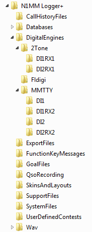
Once MMTTY has been downloaded and installed, you can proceed to use the Configurer to set up N1MM Logger+ to use it – see here. For instructions on setting up additional RX windows, see here.
Downloading and Installing 2Tone
2Tone is not installed as part of the installation of N1MM Logger+. It must be downloaded and installed separately. You cannot run 2Tone stand-alone. Most people who use 2Tone have already downloaded and configured MMTTY, and simply use 2Tone as a drop-in replacement for the MMTTY engine. If you are using 2Tone in the main DI1 or DI2 window, change the MMTTY path in the Configurer under the Digital Modes tab to point to a copy of 2Tone.exe . If you are using 2Tone in an additional RX window, configure that window for MMTTY but change the path in the setup to point to that window’s copy of 2Tone.exe . Note that if you are using 2Tone in more than one DI or RX window, every window you use it in must point to a different copy of 2Tone.exe, i.e. a copy that has been unzipped into a different folder. These folders must not be in the Program Files or Program Files (x86) path.
You can find the latest version of 2Tone in the G3YYD folder in the Files area of the N1MMLoggerPlus user group at groups.io . Download the zip file containing the latest version and unzip its contents into the folder(s) or sub-folder(s) you wish to run it from (a separate folder for each window you wish to use it in). The first time you install 2Tone in a folder, copy the entire contents of the zip file into the folder; when installing updated versions, you do not need to extract the ini files from the zip file if you wish to keep using the configuration information from the previous version.
The configuration steps in N1MM Logger+ are the same for 2Tone as for MMTTY. To configure N1MM Logger to use 2Tone as the decoder for one of the main Digital Interface windows (DI1 or DI2), follow the instructions in section 2.5 below, taking care to ensure that the DI Path points to 2Tone.exe instead of MMTTY.exe . If you wish to configure N1MM Logger to use 2Tone as the decoder in one of the additional RX windows, use the Setup > Add. RX Windows > Open Add. RX Window (4 Avail.) menu item to open the additional RX window. The first time that window opens, it will display a setup window – see section 2.6 below. Set the Window Type to MMTTY, but then in the Path box change the path to point to the appropriate copy of 2Tone.exe instead of MMTTY.exe . Click on Save.
Initially the additional RX window will be in a separate window from the main DI window. If you wish to embed the additional RX window into the DI window so that text decoded in the main and additional RX windows will appear one above the other within the DI window, select the Setup > Add. RX Windows > Enable Attached RX Windows menu item from the DI window’s menu bar. The separate window will be minimized to the task bar; if you want to close the additional RX window, or if you need to change settings in its Setup window, you can open it from the task bar.
For detailed instructions on configuration settings within 2Tone itself, see the 2Tone.pdf file in the downloaded 2Tone zip file.
Downloading and Installing Fldigi
FLdigi is not installed as part of the installation of N1MM Logger+. It must be downloaded and installed separately. It is possible to use N1MM Logger+ in RTTY and PSK contests without using fldigi. Fldigi supports a wide range of other digital modes, but most of these are rarely used for contesting. Fldigi can also be used as a receive-only CW decoder. If you want to use fldigi as a CW decoder, you need to download and install it. If you intend never to use fldigi, you can skip the rest of this section.
If you do not have a copy of fldigi and you wish to be able to use it, then before continuing with the digital setup you should download a copy of the Fldigi installer from the W1HKJ website at http://www.w1hkj.com/ . You can find a copy of the full installer for the current version of fldigi at that website. This file is a self-extracting executable, similar to the N1MM Logger+ installer. Download the file to a temporary folder and then execute it. It is recommended that you install fldigi in its own program folder and not in the N1MM Logger program folder. By default, the installer will install fldigi to C:\Program Files\Fldigi-x.xx.xx\, where x.xx.xx is the Fldigi version number. This is OK for fldigi when it is run stand-alone, but in Windows Vista, 7, or later, a copy of fldigi that is used from within N1MM Logger+ must not be placed in the Program Files or Program Files(x86) path. Therefore it is suggested that you create a new folder outside the Program Files path, such as C:\Ham Radio\fldigi, and then place any individual sub-folders for separate copies of fldigi within that folder. Another option would be to create a DigitalEngines subfolder inside the N1MM Logger+ user files folder (the one pointed to by the Help > Open Explorer on User Files Directory menu item), and then create various subfolders within DigitalEngines for copies of MMTTY, 2Tone and fldigi that you want to use with various DI windows and RX-only windows. Make a copy of fldigi.exe from the original fldigi program folder and place the copy in the new folder. You do not need to copy any of the other files; that copy of fldigi will create new configuration files the first time it is run from the Logger.
Note that older versions of fldigi only use the left channel on input; for that reason, in most SO2V installations these older versions of fldigi can only be used from Entry Window 1. Starting with Fldigi version 3.22.06, fldigi is now capable of using either sound card channel for input. In any copy of fldigi that you want to use with the right channel of the sound card, use the Configure > Sound Card menu item in the fldigi window to open the fldigi configuration window. Select the Right channel tab, and near the bottom under Receive Usage, check the Reverse Left/Right channels check box to switch fldigi to use the right channel on RX. Click on Save to save the configuration change, and then close the configuration window.
Newer versions of fldigi may default to requiring confirmation from the user before you shut them down. If that shutdown is initiated by shutting down N1MM Logger+, instead of by shutting down the DI windows and engines first, this can result in fldigi continuing to run after the Logger has shut down. This will cause problems the next time you start up the Logger. To prevent this from happening, you need to make a change in the fldigi configuration file. In each folder that fldigi is run from, find the file called fldigi_def.xml (Note: this file is created the first time fldigi is run from this location, i.e. it will not exist until after you have run that copy of fldigi at least once from within N1MM+). Right-click on the file name, select Open with… and then select Notepad or Wordpad as the program to open the file with. Look for a line that reads <CONFIRMEXIT>0</CONFIRMEXIT> or <CONFIRMEXIT>1</CONFIRMEXIT>. If you see a 1 between the two keywords, change it to a 0 and save the file. Repeat this for every copy of fldigi you use from within N1MM Logger+ (DI1, DI2, CW Reader 1 and/or CW Reader 2).
Downloading and Installing GRITTY
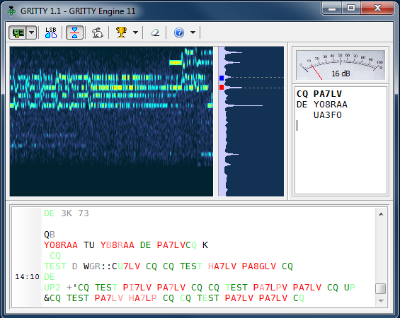
GRITTY is an innovative receive-only RTTY decoder by Alex VE3NEA (the author of DX Atlas, CW Skimmer and several other amateur radio programs). Its decoding algorithm is quite different from the algorithms used by other RTTY decoders. It can be used as one of the additional RX windows in N1MM Logger+ (see section 1.6 below) to provide additional information about received call signs and exchanges which can sometimes enable you to copy a signal even when the decoder in the main Digital Interface window is unable to decode the information successfully.
GRITTY is not installed as part of the installation of N1MM Logger+. It must be downloaded and installed separately. A zip file containing the GRITTY installer can be downloaded from http://www.dxatlas.com/Download.asp . The installer is a self-extracting executable, similar to the N1MM Logger+ installer. Download the zip file to a temporary folder and then unzip it and execute the setup program. It is recommended that you install GRITTY in its own program folder. By default this will be in the Program Files path. Unlike MMTTY, 2Tone and Fldigi, when GRITTY is used from N1MM Logger+ it can be run from the program files path. GRITTY’s configuration information is stored outside the program files path, and the interface with N1MM Logger+ creates a specially-named ini file to allow different configuration files to be used from the Logger as compared with GRITTY run stand-alone. The name of this ini file indicates which DI window (1 for SO1V, 1 or 2 for SO2R or SO2V) and which additional RX window number (1 through 4) the configuration applies to (for example, Config13.ini contains the GRITTY setup for additional RX window no. 3 from the DI-1 window). You can find the location of these configuration files from the GRITTY Help > Data Folder menu item.
GRITTY’s decoding method is based on Bayesian statistics. It performs an analysis on the received characters bit-by-bit and develops a probabilistic model, comparing incoming text to known-good call signs, common keywords and previously-decoded text in order to predict the most likely correct interpretation even in the presence of errors. In some situations, it can pick out call signs from error-filled text that would appear to be garble to other decoders. Of course, it must be used with care; while it can predict the most probable interpretation of a received string of bits and noise, this interpretation is not guaranteed to be correct. For example, it can sometimes be tricked into decoding apparent call signs from pure band noise.
GRITTY performs best when the incoming audio is not passed through a narrow filter, e.g. by using a wide SSB filter instead of narrow CW-style filters. When used with narrow filters, GRITTY can sometimes refuse to decode anything even when other decoders are succeeding. When this happens, one tactic that may work is to temporarily widen the IF filter in your rig to pass a broader range of audio frequencies. In the presence of heavy QRM such as strong nearby signals, it may be necessary to use narrow filtering in order to prevent AGC pumping from adversely affecting the other decoders using more traditional methods. Fortunately, once GRITTY has started to decode using a wider filter, the IF filter can often be narrowed back down and GRITTY will continue to decode now that it has some previously-decoded text to work with.
You can find more information on setting up and using GRITTY, and on how it works, in the GRITTY Help file.
Setting Up the Configurer
There are three tabs in the Configurer that need to be set up when configuring N1MM Logger for keyboard-to-keyboard digital modes (like RTTY and PSK). The first is the Hardware tab, where serial ports used for digital modes are set up. If you are using VOX or an interface that performs the VOX function externally (e.g. SignaLink), you do not need to configure a port for digital modes under this tab.
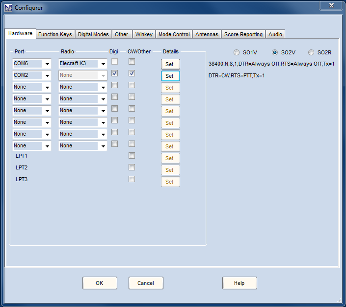
- The Digital box in the main Configurer window indicates to the Logger that this port is used for digital mode control in certain special cases, as follows:
- Use this to indicate a port that is used for an external TNC – only the Digital check box is checked for the port
- Use it to indicate a port that is used for PTT control from MMVARI
- It is possible to time-share a port (sequentially, not simultaneously) for both serial port CW keying (e.g. on DTR) and for PTT and FSK using MMTTY or 2Tone for RTTY (e.g. on RTS and TxD). If you are time-sharing a port like this, check both Digital and CW/Other for that port. When the DI window is closed, the settings in the DTR and RTS boxes will determine how the port is used; whenever the DI window is open, it will be the settings in the digital engine (e.g. MMTTY or 2Tone) that determine how the port is used. The figure above shows COM2 being used by the Logger for CW keying and by MMTTY for FSK keying
- If you use a serial port with MMTTY or 2Tone for FSK and/or PTT keying and you do not use that serial port in other modes or in MMVARI, there is no need to configure that port in the Configurer; in this case, all of the setup is done within MMTTY
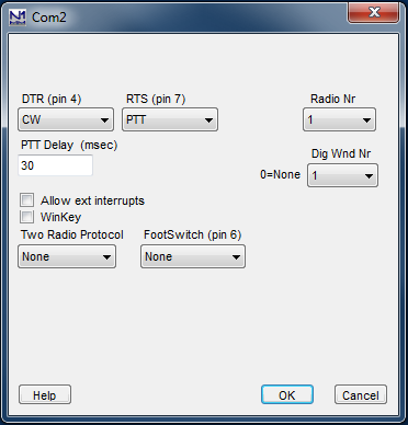
If you have checked the Digital check box, click on the Set button for the same port and select the radio number and DI window number to be associated with the port. The figure above demonstrates an example where COM2 is being used by the Logger for CW keying from DTR, and by MMTTY for FSK keying from VFO B (SO2V).
- The Radio Nr box indicates which radio this digital interface is for in SO2R mode; in SO2V and SO1V, Radio Nr is always = 1
- The Dig Wnd Nr indicates whether this port is used for DI1 or DI2. This applies to SO2V and SO2R; in SO1V, Dig Wnd Nr is always = 1
You must choose a Dig Wnd Nr for each port that has the Digital box checked; otherwise the program will not assign the port to a DI window!
The next tab to be set up is the Digital Modes tab.
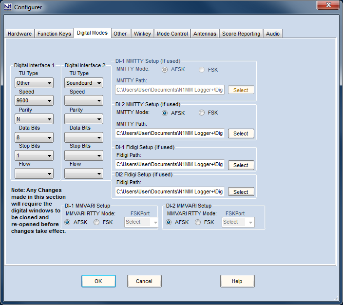
- Digital Interface 1/2 (left part of window)
- TU Type:
- None – if you do not plan to use the DI1 or DI2 digital interface
- Soundcard – for any of the sound card digital engines (MMVARI, MMTTY, 2Tone or Fldigi)
- Other – use this setting for most terminal units or TNCs (e.g. for a PK-232 or KAM TNC)
- Dxp38 – use this setting for the HAL DXP-38 terminal unit
- Speed, Parity, Data Bits, Stop Bits, Flow:
- These are only used when the TU Type is Other or Dxp38
- Set these parameters appropriately for the TNC or TU (Example settings: 9600, 8, N, 1, Xon-Xoff)
- TU Type:
- DI-1/2 MMTTY Setup (upper right part of window – this area is also used for 2Tone setup)
- MMTTY Mode: Select AFSK or FSK
- MMTTY Path: Select path to MMTTY.EXE or 2Tone.exe, including the name of the executable file (i.e. not just the path to the folder). Using the Select button for this purpose will open a File Open dialog that will allow you to navigate through the file system to find the MMTTY.exe or 2Tone.exe file, which avoids the possibility of a typing error when entering the path
- The paths for the two DI windows are not the same, since each DI window runs its own copy of MMTTY or 2Tone
You can use MMTTY with both receivers in a two-receiver setup with a single stereo sound card. You will need to install two copies of MMTTY in two separate program folders in order to allow one copy to be configured to use the left channel of the sound card and the other copy to be configured to use the right channel of the sound card.
When two copies of MMTTY are used in DI1 and DI2 with a different COM port for each copy for PSK/PTT keying, you may need to close the two DI windows separately before shutting down N1MM Logger. If both DI windows are open at the time N1MM Logger is shut down, the COM port assignments in the two copies may get confused due to a glitch in MMTTY, which means the port assignments may be wrong the next time the Logger is started up.
- DI-1/2 Fldigi Setup (midle right part of window)
- Fldigi Path: Select path to fldigi.exe (complete path, including the name of the executable file). Use the Select button to simplify the task of finding the path and typing it in correctly
- The paths for the two DI windows will normally be different in order to allow for different configurations (e.g. different audio sources) in the two copies
- Fldigi Path: Select path to fldigi.exe (complete path, including the name of the executable file). Use the Select button to simplify the task of finding the path and typing it in correctly
Starting with FLdigi version 3.22.06, you can use Fldigi with both receivers in a two-receiver setup with a single stereo sound card. You will need to install two copies of Fldigi in two separate program folders in order to allow one copy to be configured to use the left channel of the sound card and the other copy to be configured to use the right channel of the sound card on receive.
- DI-1/2 MMVARI Setup (bottom part of window)
- MMVARI RTTY Mode: Select AFSK or FSK
- FSKPort: (FSK only)
- Choose FSK8250 if you are using a true serial port or a device that can simulate a serial port and handle 5-bit codes at low speeds (this does not include most USB-to-serial adapters, but it does include some commercial interfaces designed to support FSK RTTY as well as some multi-port USB-to-serial adapters)
- When MMVARI is opened for FSK RTTY, a small window labelled MMVARIFSK1 1.04 will open, or appear on the Windows Task bar. In this window you select the COM port number and the signal line to be used for PTT (RTS or DTR). FSK keying will be done on the TxD line. If this is a USB device that simulates a serial port, check Limiting speed. You can use the _ box at the top right to minimize this window after completing the setup
- FSK8250 supports all of the RTTY speeds supported by MMVARI and the selected COM port or device
- Choose EXTFSK if you are using a regular USB-to-serial adapter
- When MMVARI is opened for FSK RTTY, a small window labelled EXTFSK 1.06 will open, or appear on the Windows Task bar. In this window you select the COM port number and the signal lines to be used for FSK keying (normally TxD) and PTT (RTS or DTR). You can use the _ box at the top right to minimize this window after completing the setup
- The only RTTY speed supported by EXTFSK is 45.45 baud
- On high-performance multi-core systems only, you may choose EXTFSK64 instead of EXTFSK. EXTFSK64 uses a more accurate timing mechanism than EXTFSK, but this mechanism uses significant CPU resources. EXTFSK64 is not appropriate for use on XP based systems or hardware running older dual-core Intel/AMD CPUs or Atom based CPUs. On systems that are capable of supporting it, EXTFSK64 can key FSK from LPT ports as well as USB-to-serial adapters. See http://www.qsl.net/ja7ude/extfsk/indexe.html for more detailed information on EXTFSK64
- When MMVARI is opened for FSK RTTY, a small window labelled EXTFSK 2.0 will open, or appear on the Windows Task bar. In this window you select the COM or LPT port number and the signal lines to be used for FSK keying (normally TxD) and PTT (RTS or DTR). You can use the _ box at the top right to minimize this window after completing the setup
- EXTFSK64 can key FSK at speeds other than 45.45 baud (e.g. 75 baud)
- Choose FSK8250 if you are using a true serial port or a device that can simulate a serial port and handle 5-bit codes at low speeds (this does not include most USB-to-serial adapters, but it does include some commercial interfaces designed to support FSK RTTY as well as some multi-port USB-to-serial adapters)
You can use MMVARI with both receivers in a two-receiver setup with a single stereo sound card. In the DI Window’s Digital Setup dialog box under the MMVARI Setup tab, simply configure the DI1 SoundCard to use the left channel and the DI2 SoundCard to use the right channel.
The third tab to be set up is the Mode Control tab, which determines what mode the radio will be set to use in RTTY and PSK.
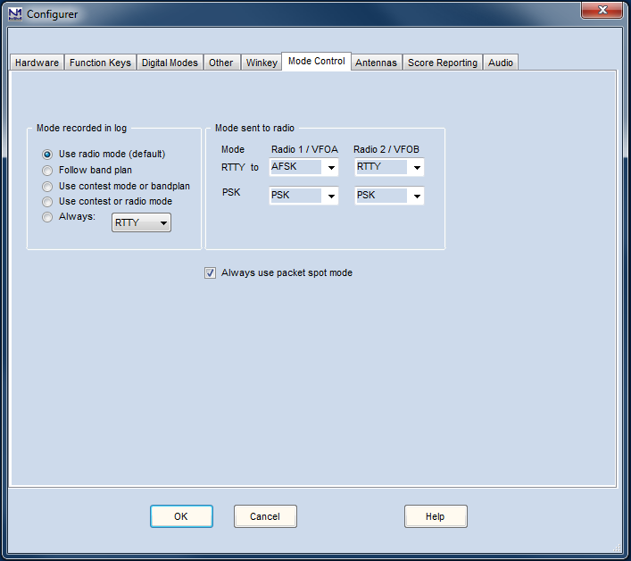
This example is for a radio or radios with separate modes for FSK, AFSK and PSK (e.g. Elecraft K3 using FSK D, AFSK A and DATA A respectively). This particular setup uses AFSK from DI-1 (radio 1) and FSK from DI-2 (radio 2). The appropriate choices in the list boxes under Mode sent to radio will depend on the particular radio type (see Supported radios). For FSK RTTY, the correct choice will normally be RTTY. For AFSK RTTY, depending on the radio the appropriate choice might be AFSK or LSB/USB (or if you are using Fldigi and your radio has an upper sideband digital audio mode, perhaps PSK). For PSK31 and other sound card modes, the radio mode would be PSK (if available), AFSK-R (on some radios) or USB on most radios. For more information, see the Configurer page under the Config >Mode Control tab.
Additional RX Windows for RTTY
N1MM Logger+ supports up to four additional RTTY receive-only windows for each DI window. The purpose of these windows is to allow simultaneous use of more than one decoding algorithm on the same audio input. While it is possible, by using wide bandwidth filters, to use the additional windows to decode different signals from the one in the main DI windows, the normal use of the additional windows is to decode the same signal as the one in the main window, using a different decoding method to improve the overall ability to decode signals in difficult situations.
These receive-only windows may use additional copies of MMTTY or 2Tone, configured with different “profiles” (e.g. multipath, fluttered, different detection algorithms). Alternatively, they can be used with a copy of Fldigi or GRITTY, or with additional TNCs or TUs. You can use any of the transmit-capable digital interface engines in the main DI window (MMTTY, 2Tone, MMVARI, Fldigi or a TNC/TU). The additional RX windows may be configured to use either the same sound-card interface engine as the main DI window with a different profile, or a different interface engine, including GRITTY (read-only), but not including MMVARI (MMVARI can only be used in the main DI window).
The receive-only windows are invoked from the DI window’s Setup > Add. RX Windows > Open Add. Rx Window (4 Avail.) menu item – the number in the menu item indicates how many of these windows are unused and still available. The first time one of these windows is opened, its Setup window will be displayed.
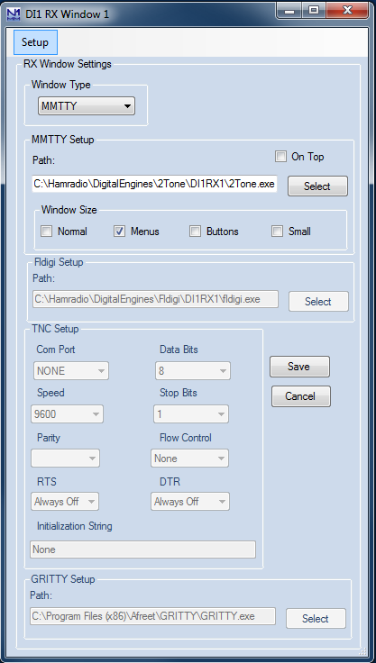
The setup information that must be entered includes the engine type (MMTTY, TNC, Dxp38, GRITTY or Fldigi – the MMTTY setting is also used for 2Tone), the path to the copy of MMTTY/2Tone, Fldigi or GRITTY for that window (if used), and/or the COM port information for a TNC (if used). Note that the path is the path to the .exe or executable file, not just the path to the directory in which it is located, i.e. when you use the Select button to find the engine, you must click on the actual executable file, then on the Open button in the File Open window. Alternatively, you can double-click on the executable file in the window.
After the setup information has been entered, click on the Save button to register the information. The additional RX window must be closed and re-opened (it may do this automatically), and then it will be available for use. If the engine type is MMTTY, Fldigi or GRITTY, a separate spectrum display window is also opened for the software digital engine, and can be used as a tuning indicator. Once the additional RX window is active, you can click on call signs and exchanges in the text window to pass them to the Entry window, the same as you can in the main DI window.
It is possible to embed or attach a copy of the additional RX windows directly into the RX window area in the main Digital Interface DI window, using the DI window’s Setup > Add. RX Windows > Enable Attached RX Windows menu item. Each such attached window is denoted with its number (1, 2, 3 or 4), which is normally on a green background. If the number is clicked on with the mouse, the background color changes to yellow and the text in that window is frozen temporarily, similarly to the green/yellow bar on the left of the main receive window and the regular additional RX windows.
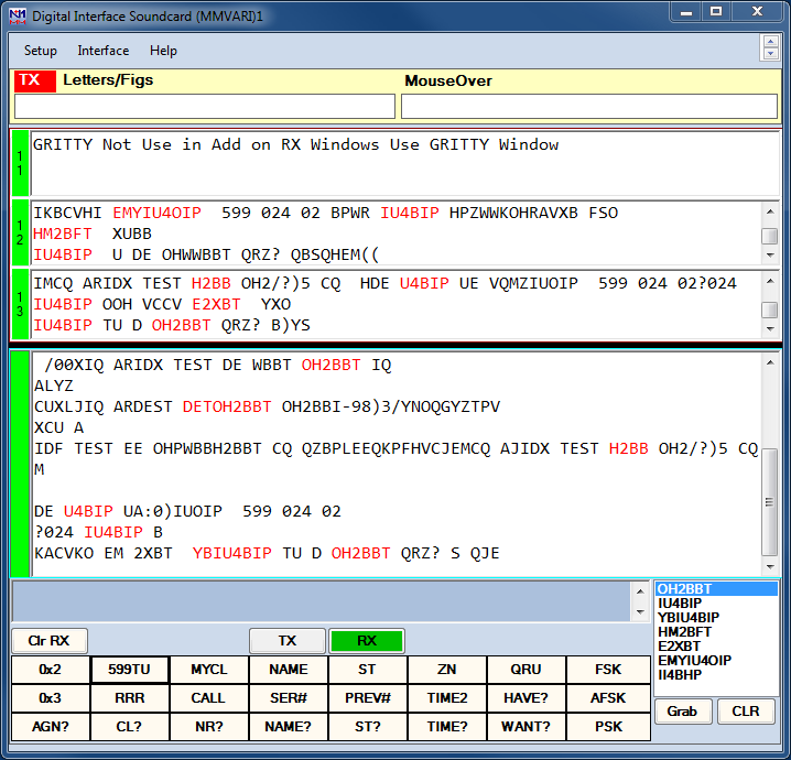
The separate additional RX window(s) is/are minimized to the task bar when the attached windows are enabled, but they may be restored from the task bar in order to be able to change setup parameters or to close the additional RX window. The icon(s) for the additional RX window(s) are grouped together with the icons for N1MM Logger+ on the task bar. If any of the additional RX windows use sound card software for decoding, the spectrum display windows for those digital engines may also be mimimized to icons on the task bar, but these will be separate from the Logger icons; note that the icon for the digital engine (MMTTY – black crossed ellipses on a white background; 2Tone – 2T; GRITTY – green crossed ellipses; or Fldigi – miniature waterfall) controls the display for the digital engine only, not the RX text window. In the screen shot below, as a result of hovering the mouse over the the N1MM Logger+ icons they have been expanded to thumbnail images above the task bar. The title of each thumbnail indicates which window will be restored if you click on that thumbnail.
If Fldigi is used in parallel with other decoder engines, you need to be aware of the fact that fldigi assumes by default that the radio is in USB, whereas the other decoders assume LSB. If your radio is in LSB (this includes the FSK RTTY mode in amateur transceivers), you will need to tell fldigi to reverse its tones using the Rev button in the corresponding DI or additional RX window. This Rev button is not accessible from the attached RX-only windows; if you have enabled attached windows, you will need to restore the non-attached window to gain access to the Rev button for that copy of fldigi. Alternatively, if the radio is in USB (or FSK-R, etc.), fldigi will be on the correct sideband but you will need to reverse the tones in the other decoders using their respective reverse settings in the digital engine windows.
The Digital Interface Window
The Digital Interface window, or DI window, is nearly the same regardless of which type of interface (MMTTY, MMVARI, FLDIGI or TNC) is being used. Its appearance (font sizes and foreground and background font colors) can be customized using the Skins, Colors and Fonts dialog window (main Entry window, Config > Manage Skins, Colors and Fonts).
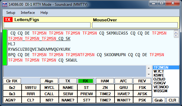
The Digital Interface is opened from the Entry window’s Window > Digital Interface menu item. If you are using two entry windows (SO2V/SO2R), each entry window has a separate DI window associated with it – DI1 with the VFO A/Radio 1 Entry window, and DI2 with the VFO B/Radio 2 Entry window. Each DI window is opened from its corresponding Entry window’s menu bar. If the digital “engine” chosen in a Digital Interface window is sound card software (MMTTY, MMVARI, Fldigi or 2Tone), a separate window including a tuning display and various other digital engine-specific information will also be opened when the Digital Interface window is opened – see the section of the manual relevant to the specific digital engine that has been selected.
The DI window may be configured either in scrolling mode or in non-scrolling mode. Scrolling mode is the same as N1MM Logger Classic – new text is always added below previous text (i.e. usually on the bottom line of the RX window), and previously received lines scroll off the top of the window. Non-scrolling mode is new in N1MM Logger+ – previously received text does not move, but stays where it was first displayed until it is overwritten with new text. The line on which incoming text is being displayed is indicated with an underline, and this line moves steadily down the screen until it reaches the bottom, after which the top line in the window becomes the new incoming text line. The advantage of this mode is that received call signs and exchanges do not move, making them easier to click on.
The Digital Interface caption displays either the offset frequency (radio’s dial frequency +/- audio frequency) or the radio’s dial frequency, depending on what you have chosen in the Digital Setup.
- TX – Indicator to show which window has transmit focus (useful when using two sessions like SO2R)
- Letters/Figs – Shows the text under the mouse in reverse case (letters/figures switched)
- MouseOver – Shows the text under the mouse; this is the text that would be selected by a mouse click
Top RX window – This is the receive window. Depending on the scrolling option you choose in the Digital Interface’s Setup window, you can make this window either a scrolling window (old text scrolls off the top of the window as new lines are inserted at the bottom), or non-scrolling (new text appears on the active line, which is underlined; each time a new line starts, the text that was previously in the next line down is cleared and that line becomes the new current line; if the current line is at the bottom of the RX window, the line at the top of the window is cleared and becomes the current line where new text is entered). Some users find it easier to use a non-scrolling window where text does not move after it is entered (so incoming newlines do not cause text to scroll up just as you want to click on it). Other users find it easier to use a scrolling window so that new incoming text is always near the bottom of the window where they don’t have to move the mouse very far to click on it. The Logger gives you the choice.
There are 2 ways of moving a callsign from the RX window into the callsign box in the Entry window. You can single click on a callsign and it will transfer over to the main logging window, or, whenever a callsign is detected in the RX window it will be sent to the callsign grab window for easy movement to the logging window by clicking the Grab button or using a function key with a {GRAB} macro in it.
Pause bar (green/yellow bar at the left of the RX window) -By clicking on the colored bar on the left you can pause input to the receive window to scroll back through the (last 2000 lines of) text using the scroll bars. When the window is paused the color of the bar will turn yellow. To turn input to the window back on click in the bar again and everything that was to be printed to the window will now enter the window. When the receive window is paused it is possible to select and copy text in the window.
Bottom TX window – This is the transmit window, a free form typing window. In the screen shot above, it is the darker grey area below the received text window and above all the buttons. If you click on the TX button the cursor will be placed into this window and whatever is typed will be sent. The size is static and doesn’t change size (2 lines). For TNC users: when not transmitting, anything typed in the TX Window will be sent to the TNC. Used to send TNC commands to change settings etc.
Callsign Textbox and Grab – When a callsign is encountered in one of the receive windows it will be placed in the Grab list in this textbox and when you press the Grab button it will transfer the callsign over to the main Entry window. The grab callsign window holds the last 10 callsigns seen in the RX window. The most current one is at the top and is highlighted. Dupe callsigns will not be shown in the grab window. The Sort Order in the grab window can be selected by right-clicking; you can choose either Last In First Out or First In First Out as the sort order
Callsign not added to grab List
If the callsign in the callsign field in the Entry window is the same as the callsign in the received text, the call in the Entry window does not get placed into the grab call list. Clicking on a callsign in the RX window to move it into the Entry window will remove that callsign from the Grab list.
Message buttons – The Digital Interface window can display 0, 8, 16 or 24 extra message buttons for preprogrammed messages. Configuring these message buttons is done in the Digital Interface window under ‘Setup | Settings’ or by right clicking on them, which brings up the Digital setup dialog. The width of these message buttons dynamically adjusts in relation to the width of the interface window
- Clr RX – Clear the receive window (also possible using the right click menu, unless the Rt Click = Enter option has been selected)
- Align (MMTTY and Fldigi only) – This is used to move the signal that you are copying into the passband of your filters. Set the frequency in the setup area. For example, if your filters are centered on 2210 Hz, RTTY signals close to the 2125/2295 Hz pair will be copied well, but signals at higher or lower frequencies may not make it through the filters. If you click on a signal at a frequency in the waterfall that is not close to the nominal 2125/2295 pair, it may not decode very well. After clicking on the signal, if you click on the Align button your transceiver will be retuned to line the signal up on the configured frequency. This is essential in FSK where the transmit frequencies are fixed in the radio, and useful also in AFSK if you want to use narrow filters
- Note that when you are using the MMVARI interface engine, the Align button appears on the MMVARI window instead of on the Digital Interface window
- TX – Start the RTTY transmission, the transceiver is keyed. Will be colored Red when transmitting
- RX – Stop the RTTY transmission – the transceiver changes back to receive. Will be colored Green when in receive
- HAM (MMTTY only) – Restore the MMTTY frequency and shift settings to the HAM default
- AFC (MMTTY only) – Can be used to turn MMTTY’s AFC on or off (colored background means AFC is on)
- Lock (Fldigi only) – Locks the transmit frequency at the current location. If you move the receive frequency, e.g. by clicking elsewhere in the waterfall, the transmit frequency does not change. Used for operating split
- Rev (MMTTY and Fldigi only) – In sideband-sensitive modes like RTTY, reverses the tones (e.g. opposite sideband)
- Grab – Transfer the selected callsign in the Callsign textbox to the callsign field on the main Logger Entry window. Once the callsign is filled, whatever you click on next will fill the next exchange box. When the Digital Interface is in transmit, calls are not added to the Grab window
- CLR – Clear the Grab list
Receive Window Callsign Colors
When a callsign is recognized in the receive input stream the callsign will be colored according to the same color scheme that is used in the Bandmap Window and brought to the Grab window. Valid callsigns that are separated by spaces are always recognized, and optionally the Search routine can be used to search for known call signs from the Master.scp file in garbage text strings. When the search in garbage text is enabled and two calls are found in the same string, only the last one gets highlighted. Also, if the call sign being copied contains a shorter call sign that is in the Master.scp file, using the search in garbage feature may result in the shorter call sign being recognized instead of the longer one. The highlighted calls in text strings are clickable.
If the “Use Generic Routines” option is chosen under Callsign Validity and Highlight in the Digital Setup, anything that looks like a callsign will be highlighted with a color that indicates its multiplier status using the same colors as in the Bandmap and Entry window. If the “Use Master.scp File” option is chosen, callsigns that are not in the Master.scp file will be highlighted in yellow in addition, either by changing the background to yellow (if the multiplier color is in the foreground), or by changing the text color to yellow (if the multiplier color is in the background). Regardless of which option is chosen, anything that passes the check routines and looks like a callsign will be placed in the Grab window.
Mouse Assignments
- Left mouse key clicking
- Single clicking on a callsign grabs it and places it in the Callsign field on the Entry Window dialog
- Single clicking on Exchange info etc. (not on a callsign) grabs it and places it in the Exchange field on the Entry Window dialog. If there are two or more exchange fields, as in some contests, you must take care to ensure that the keyboard cursor is in the exchange box corresponding to the element you are clicking on; if you click on an exchange element while the cursor is in the wrong box, the element will be transferred to the wrong place, and if there was something else there, it will be overwritten
- Note: The callsign field must be filled first! If there is nothing in the callsign field, single clicking on exchange info will not do anything
- Double clicking on a callsign grabs it and overrides the current information in the Callsign field on the Entry Window dialog
- Ctrl+Single clicking – will force what ever you are clicking to be sent to the box containing the typing cursor in the Entry window (You may need to click first in the Entry window, or else use the space bar, to select the box where you want to place the new data)
- Shift+Single clicking – will cause the moused over text to be Letter/Figs converted on the fly while sending to Entry Window (only in RTTY Mode)
- Alt+Single clicking – if Digital Call Stacking is enabled, will transfer the call sign being clicked on to the Bandmap call stack (see Single Operator Call Stacking for more information)
- Right mouse key clicking on RX window
- Will give a menu only when the menu item ‘RT Click = Return NOT menu’ is NOT selected!
- Clear RX – Clear the receive window. This receive buffer can contain a maximum of 10,000 characters
- Output to Text File – Output the received text to a text file named RTTY1.txt
- Help – Show the help file for this window
- Will give a menu only when the menu item ‘RT Click = Return NOT menu’ is NOT selected!
- Right mouse key clicking on TX window
- Will give a menu only when the menu item ‘RT Click = Return NOT menu’ is NOT selected!
- Clear TX – Clear the transmit window
- Paste – Place the TX text in the Paste buffer
- Will give a menu only when the menu item ‘RT Click = Return NOT menu’ is NOT selected!
- Right mouse key clicking in GRAB window
- Gives a menu:
- Clear List – Clear the entire grab window
- Clear Selected Call – Clear the selected call in the grab window
- Sort Order – Choose the order in which call signs are pulled from the grab window:
- Last In, First Out
- First In, First Out
- Gives a menu:
Keyboard Assignments
- Alt+T – Toggle TX/RX, when in TX the cursor will be set to the TX window of the active interface
- Ctrl+K – Toggle TX/RX and move the cursor into the DI’s TX window to send manual information using the keyboard; press Esc or click on the RX button to terminate manual sending
- Alt+G – Grab most recent callsign from callsign textbox. Upon grabbing that callsign gets deleted from the grab list
- Ctrl+Left/Right arrows – When two radios are configured in SO2R or a dual-receiver radio is used in SO2V, and two digital windows are open, pressing Ctrl+Left arrow or Ctrl+Right arrow will swap from one active Digital Interface to the other. Digital Interface 1 will follow VFO A/Radio 1, Digital Interface 2 will follow VFO B/Radio 2
The Digital Interface – Menu Selections
The digital interface has a menu at the top which varies slightly depending on which type of interface is selected under the Digital Modes tab in the Configurer.
Configurer Selection: Soundcard
- Setup
- Settings – Opens the Digital Setup window; see the section on ‘The Digital Interface – Setup’ below
- Turn AutoTRXUPdate On/Off
- If your radio’s dial displays the actual transmitted frequency (i.e. the Mark frequency in FSK RTTY), you would turn this option off
- If your radio’s dial displays the suppressed carrier frequency (e.g. SSB mode), you would turn this option on. This causes the program to add (USB) or subtract (LSB) the audio frequency from the digital engine to/from the radio’s dial frequency so that the frequency that appears in the Entry window, the Bandmap, the log and spotted to the DX cluster is the actual transmitted frequency, not the suppressed carrier frequency
If the AutoTRXUpdate option is turned on, it takes effect whenever the DI window is open. If you leave the DI window open and switch to CW or SSB, the offset will continue to be applied, and the frequencies in the Entry window, Bandmap and your log will be incorrect. You should always close the DI window when switching from digital modes to other modes. Also, if you are likely to want to use a non-digital mode the next time you start the program, you should close the DI window before shutting down N1MM Logger in order to ensure that the DI window does not cause this option to be applied the next time you start the Logger.
- Bring to Foreground when made Active – Bring the Digital Interface and Engine to the foreground when its Entry window has focus
- This adds ability to stack Digital Interfaces and Engines and have the correct one on top when the associated Entry window has focus
- SoundCard
- RX Mixer – Shows the Record control mixer dialog from the Windows operating system. Only for Windows versions XP and earlier
- TX Mixer – Shows the Play control mixer dialog from the Windows operating system. Only for Windows versions XP and earlier
- These menu items are not available when using the Fldigi engine. They are also not available in Windows 7, 8, 10, 11 and Vista
- Setup MMTTY – The MMTTY setup is shown. This menu item is only visible when MMTTY is selected
- AFC On/Off with CQ – If set then the AFC will turn on with CQ message or TU messages. Turning AFC on when soliciting new callers with a CQ or QRZ message can help tune in off-frequency callers
- NET On/Off with Run Change – Option to turn Net function on in S&P and off in Running mode. In S&P mode, you normally want to transmit on the same frequency you are receiving on; in AFSK, turning NET on ensures this. In Run mode, you normally leave NET off in order to allow the receiver to track off-frequency callers without moving your TX frequency
- Turn Hover Mode On/Off – With this option selected, when the mouse is hovered over a valid callsign the callsign is automatically transferred to the Entry window’s callsign box without having to click on it. This option is most effective when used in combination with the RT Click = Return NOT menu option
- Note: Your own call is excluded from being picked up
- RT Click = Return NOT menu – When this option is selected, a right-click in the RX window will perform the same functions as pressing the Enter key. This is designed to work with ESM; in ESM, in a routine QSO pressing the Enter key automatically sends the next message in the normal QSO sequence. For example, when CQing, once a callsign has been placed in the callsign box (either by left-clicking on it or using the Hover mode option), right-clicking will send the exchange and move the cursor to the exchange box, left-clicking on the received exchange will transfer the exchange to the entry window and right-clicking will send the TU message and log the contact. A complete QSO can be performed with simply a couple of left-clicks and a couple of right-clicks. As always with ESM, you need to be aware of the current ESM state. If the exchange data is not yet valid, or if the cursor is in the callsign box after the exchange data has been entered, the ESM state and the resulting action may not be what you expect
- With RtClicked enabled Don’t drop On-Deck Call – modifies the behavior of the above option when there is an “on-deck” call sign in the frame above the Call Sign box in the Entry window. The defaulr behavior is that if the call sign box is empty and there is a call sign in the frame, right-clicking in the RX window will automatically transfer the on-deck call sign into the call sign. Checking this option turns this off, i.e. it stops the call from dropping from the on-deck spot into the call sign box when the call sign box is empty, ESM is on and the My Call button (F4) is highlighted.
- Send Text File – Send a text file. A file open dialog will appear from which the file to be sent can be selected
- Output Main RX Window to Text File – When this is checked, text that is displayed in the main RX window will be saved to a text file in the ExportFiles directory in the N1MM Logger+ user files area. The file name will be date stamped (mmddyyyy), as in 05312012DigitalInterface1Output.txt (for DI1)
- Digital Call Stacking – Used together with the {LOGTHENPOP} macro. See Single Operator Call Stacking for more information
- Enable using First In First Out – Enables the Digital Call Stacking feature. Calls are popped off the stack in the order they were placed there
- Enable using Last In First Out – Enables the Digital Call Stacking feature. Calls are popped off the stack in reverse order, i.e. most recent first
- Enable using FIFO Mults First – Enables the Digital Call Stacking feature. Calls are popped off the stack in order of their multiplier value. In those contests where one QSO can yield 2 or 3 mults, the higher-mult calls will be taken first. Among calls with the same multiplier value, calls are popped in FIFO order, i.e. in the order they were placed there
- Disabled – Disables the Digital Call Stacking feature
- Use RX Window Callsign Pause Routines – When this option is selected, moving the mouse in the RX window over a valid callsign while the callsign box in the Entry window is empty will cause incoming text to stop appearing and the RX window to pause scrolling. At this point you can either click on the callsign to transfer it into the Entry window, display any incoming text that was held back during the pause and resume scrolling, or simply move the mouse off the callsign to display any held incoming text and resume normal scrolling. Also with this option selected, when the left mouse button is clicked in the RX window to select text the RX window will pause until the mouse button is released after the text has been selected, at which point the selected text will be copied to the clipboard, any held incoming text will be displayed and normal scrolling will resume. If there is a scrollbar present in the RX window, moving the scroll bar will cause incoming text to be paused until either text has been selected and the mouse has been released, the pause strip at the left side of the window is clicked, or the right mouse button is clicked in the RX window
- Add. RX Windows
- Enable Attached RX Windows – After one or more additional RX window(s) has/have been set up using the last submenu item below, this option can be selected in order to attach or embed small RX text displays from the additional RX window(s) into the main DI window. When the additional RX windows are attached to the main RX window using this option, the attached windows appear above the main RX window. The non-attached RX windows are minimized to the task bar when the attached windows are enabled, but they may be restored from the task bar in order to see more text than is visible in the attached window, to access the setup options, or to close the additional RX window without closing the main DI window. The task bar icon for the additional RX window is grouped with the main N1MM Logger icons. If the additional RX window is using a software decoder, there will also be a separate task bar icon for the digital engine; do not confuse the two task bar icons
- Open Add. RX Window (4 Avail.) – This allows you to open an auxiliary RX window for diversity decoding of the same RTTY signal, e.g. by using a TNC in the main DI window and MMTTY or 2Tone in the auxiliary window, or by using a different copy of MMTTY or 2Tone with a different decoding algorithm to decode the same audio input. There are up to 4 such windows available (the remaining number available appears in the menu). Each additional window is associated with either DI1 or DI2, depending on which DI window menu was used to open it. There is a separate Setup dialog for each additional RX window, which is accessible from the menu bar at the top of the additional window. The first time an additional RX window is opened, its setup dialog will automatically be displayed. The decoder type (MMTTY, TNC or DXP38 – use MMTTY for 2Tone), and the path to the program or the COM port information for a TNC must be filled in before the additional RX window can be used. Once all of the additional RX windows you intend to open from either DI window have been set up and tested, you can use the Enable Attached RX Windows option to attach the additional windows to the main DI window
Configurer Selection: OTHER
- Setup
- Settings – Opens the Digital Setup window; see the section on ‘The Digital Interface – Setup’ below
- Turn AutoTRXUPdate On/Off
- If your radio’s dial displays the actual transmitted frequency (i.e. the Mark frequency in FSK RTTY), you would turn this option off
- If your radio’s dial displays the suppressed carrier frequency (e.g. SSB mode), you would turn this option on. This causes the program to add (USB) or subtract (LSB) the audio frequency from the digital engine to/from the radio’s dial frequency so that the frequency that appears in the Entry window, the Bandmap, the log and spotted to the DX cluster is the actual transmitted frequency, not the suppressed carrier frequency
If the AutoTRXUpdate option is turned on, it takes effect whenever the DI window is open. If you leave the DI window open and switch to CW or SSB, the offset will continue to be applied, and the frequencies in the Entry window, Bandmap and your log will be incorrect. You should always close the DI window when switching from digital modes to other modes. Also, if you are likely to want to use a non-digital mode the next time you start the program, you should close the DI window before shutting down N1MM Logger in order to ensure that the DI window does not cause this option to be applied the next time you start the Logger.
- Bring to Foreground when made Active – Bring the Digital Interface and Engine to the foreground when its Entry window has focus
- This adds ability to stack Digital Interfaces and Engines and have the correct one on top when the associated Entry window has focus
- Turn Hover Mode On/Off – With this option selected, when the mouse is hovered over a valid callsign the callsign is automatically transferred to the Entry window’s callsign box without having to click on it. This option is most effective when used in combination with the RT Click = Return NOT menu option
- Note: Your own call is excluded from being picked up
- RT Click = Return NOT menu – When this option is selected, a right-click in the RX window will perform the same functions as pressing the Enter key. This is designed to work with ESM; in ESM, pressing the Enter key automatically sends the next message in the normal QSO sequence. For example, when CQing, once a callsign has been placed in the callsign box (either by left-clicking on it or using the Hover mode option), right-clicking will send the exchange and move the cursor to the exchange box, left-clicking on the received exchange will transfer the exchange to the entry window and right-clicking will send the TU message and log the contact. A complete QSO can be performed with simply a couple of left-clicks and a couple of right-clicks
- With RtClicked enabled Don’t drop On-Deck Call – modifies the behavior of the above option when there is an “on-deck” call sign in the frame above the Call Sign box in the Entry window. The defaulr behavior is that if the call sign box is empty and there is a call sign in the frame, right-clicking in the RX window will automatically transfer the on-deck call sign into the call sign. Checking this option turns this off, i.e. it stops the call from dropping from the on-deck spot into the call sign box when the call sign box is empty, ESM is on and the My Call button (F4) is highlighted.
- Send Text File – Send a text file. A file open dialog will appear from which the file to be sent can be selected
- Output Main RX Window to Text File – When this is checked, text that is displayed in the main RX window will be saved to a text file in the ExportFiles directory in the N1MM Logger+ user files area. The file name will be date stamped (mmddyyyy), as in 05312012DigitalInterface1Output.txt (for DI1)
- Digital Call Stacking – Used together with the {LOGTHENPOP} macro. See Single Operator Call Stacking for more information
- Enable using First In First Out – Enables the Digital Call Stacking feature. Calls are popped off the stack in the order they were placed there
- Enable using Last In First Out – Enables the Digital Call Stacking feature. Calls are popped off the stack in reverse order, i.e. most recent first
- Enable using FIFO Mults First – Enables the Digital Call Stacking feature. Calls are popped off the stack in order of their multiplier value. In those contests where one QSO can yield 2 or 3 mults, the higher-mult calls will be taken first. Among calls with the same multiplier value, calls are popped in FIFO order, i.e. in the order they were placed there
- Disabled – Disables the Digital Call Stacking feature
- Use RX Window Callsign Pause Routines – When this option is selected, moving the mouse in the RX window over a valid callsign while the callsign box in the Entry window is empty will cause incoming text to stop appearing and the RX window to pause scrolling. At this point you can either click on the callsign to transfer it into the Entry window, display any incoming text that was held back during the pause and resume scrolling, or simply move the mouse off the callsign to display any held incoming text and resume normal scrolling. Also with this option selected, when the left mouse button is clicked in the RX window to select text the RX window will pause until the mouse button is released after the text has been selected, at which point the selected text will be copied to the clipboard, any held incoming text will be displayed and normal scrolling will resume. If there is a scrollbar present in the RX window, moving the scroll bar will cause incoming text to be paused until either text has been selected and the mouse has been released, the pause strip at the left side of the window is clicked, or the right mouse button is clicked in the RX window
- Add. RX Windows
- Enable Attached RX Windows – After one or more additional RX window(s) has/have been set up using the last submenu item below, this option can be selected in order to attach or embed small RX text displays from the additional RX window(s) into the main DI window. When the additional RX windows are attached to the main RX window using this option, the attached windows appear above the main RX window. The non-attached RX windows are minimized to the task bar when the attached windows are enabled, but they may be restored from the task bar in order to see more text than is visible in the attached window, to access the setup options, or to close the additional RX window without closing the main DI window
- Open Add. RX Window (4 Avail.) – This allows you to open an auxiliary RX window for diversity decoding of the same RTTY signal, e.g. by using a TNC in the main DI window and MMTTY or 2Tone in the auxiliary window, or by using a different copy of MMTTY or 2Tone with a different decoding algorithm to decode the same audio input. There are up to 4 such windows available (the remaining number available appears in the menu). Each additional window is associated with either DI1 or DI2, depending on which DI window menu was used to open it. There is a separate Setup dialog for each additional RX window, which is accessible from the menu bar at the top of the additional window. The first time an additional RX window is opened, its setup dialog will automatically be displayed. The decoder type (MMTTY, TNC or DXP38 – use MMTTY for 2Tone), and the path to the program or the COM port information for a TNC must be filled in before the additional RX window can be used. Once all of the additional RX windows you intend to open from either DI window have been set up and tested, you can use the Enable Attached RX Windows option to attach the additional windows to the main DI window
Configurer Selection: DXP38
- Setup
- Settings – Opens the Digital Setup window; see the section on ‘The Digital Interface – Setup’ below
- Turn AutoTRXUPdate On/Off
- If your radio’s dial displays the actual transmitted frequency (i.e. the Mark frequency in FSK RTTY), you would turn this option off
- If your radio’s dial displays the suppressed carrier frequency (e.g. SSB mode), you would turn this option on. This causes the program to add (USB) or subtract (LSB) the audio frequency from the digital engine to/from the radio’s dial frequency so that the frequency that appears in the Entry window, the Bandmap, the log and spotted to the DX cluster is the actual transmitted frequency, not the suppressed carrier frequency
If the AutoTRXUpdate option is turned on, it takes effect whenever the DI window is open. If you leave the DI window open and switch to CW or SSB, the offset will continue to be applied, and the frequencies in the Entry window, Bandmap and your log will be incorrect. You should always close the DI window when switching from digital modes to other modes. Also, if you are likely to want to use a non-digital mode the next time you start the program, you should close the DI window before shutting down N1MM Logger in order to ensure that the DI window does not cause this option to be applied the next time you start the Logger.
- Bring to Foreground when made Active – Bring the Digital Interface and Engine to the foreground when its Entry window has focus
- This adds ability to stack Digital Interfaces and Engines and have the correct one on top when the associated Entry window has focus
- Turn Hover Mode On/Off – With this option selected, when the mouse is hovered over a valid callsign the callsign is automatically transferred to the Entry window’s callsign box without having to click on it. This option is most effective when used in combination with the RT Click = Return NOT menu option
- Note: Your own call is excluded from being picked up
- RT Click = Return NOT menu – When this option is selected, a right-click in the RX window will perform the same functions as pressing the Enter key. This is designed to work with ESM; in ESM, pressing the Enter key automatically sends the next message in the normal QSO sequence. For example, when CQing, once a callsign has been placed in the callsign box (either by left-clicking on it or using the Hover mode option), right-clicking will send the exchange and move the cursor to the exchange box, left-clicking on the received exchange will transfer the exchange to the entry window and right-clicking will send the TU message and log the contact. A complete QSO can be performed with simply a couple of left-clicks and a couple of right-clicks
- With RtClicked enabled Don’t drop On-Deck Call – modifies the behavior of the above option when there is an “on-deck” call sign in the frame above the Call Sign box in the Entry window. The defaulr behavior is that if the call sign box is empty and there is a call sign in the frame, right-clicking in the RX window will automatically transfer the on-deck call sign into the call sign. Checking this option turns this off, i.e. it stops the call from dropping from the on-deck spot into the call sign box when the call sign box is empty, ESM is on and the My Call button (F4) is highlighted.
- Send Text File – Send a text file. A file open dialog will appear from which the file to be sent can be selected
- Output Main RX Window to Text File – When this is checked, text that is displayed in the main RX window will be saved to a text file in the ExportFiles directory in the N1MM Logger+ user files area. The file name will be date stamped (mmddyyyy), as in 05312012DigitalInterface1Output.txt (for DI1)
- Digital Call Stacking – Used together with the {LOGTHENPOP} macro. See Single Operator Call Stacking for more information
- Enable using First In First Out – Enables the Digital Call Stacking feature. Calls are popped off the stack in the order they were placed there
- Enable using Last In First Out – Enables the Digital Call Stacking feature. Calls are popped off the stack in reverse order, i.e. most recent first
- Enable using FIFO Mults First – Enables the Digital Call Stacking feature. Calls are popped off the stack in order of their multiplier value. In those contests where one QSO can yield 2 or 3 mults, the higher-mult calls will be taken first. Among calls with the same multiplier value, calls are popped in FIFO order, i.e. in the order they were placed there
- Disabled – Disables the Digital Call Stacking feature
- Use RX Window Callsign Pause Routines – When this option is selected, moving the mouse in the RX window over a valid callsign while the callsign box in the Entry window is empty will cause incoming text to stop appearing and the RX window to pause scrolling. At this point you can either click on the callsign to transfer it into the Entry window, display any incoming text that was held back during the pause and resume scrolling, or simply move the mouse off the callsign to display any held incoming text and resume normal scrolling. Also with this option selected, when the left mouse button is clicked in the RX window to select text the RX window will pause until the mouse button is released after the text has been selected, at which point the selected text will be copied to the clipboard, any held incoming text will be displayed and normal scrolling will resume. If there is a scrollbar present in the RX window, moving the scroll bar will cause incoming text to be paused until either text has been selected and the mouse has been released, the pause strip at the left side of the window is clicked, or the right mouse button is clicked in the RX window
- Add. RX Windows
- Enable Attached RX Windows – After one or more additional RX window(s) has/have been set up using the last submenu item below, this option can be selected in order to attach or embed small RX text displays from the additional RX window(s) into the main DI window. When the additional RX windows are attached to the main RX window using this option, the attached windows appear above the main RX window. The non-attached RX windows are minimized to the task bar when the attached windows are enabled, but they may be restored from the task bar in order to see more text than is visible in the attached window, to access the setup options, or to close the additional RX window without closing the main DI window
- Open Add. RX Window (4 Avail.) – This allows you to open an auxiliary RX window for diversity decoding of the same RTTY signal, e.g. by using a TNC in the main DI window and MMTTY or 2Tone in the auxiliary window, or by using a different copy of MMTTY or 2Tone with a different decoding algorithm to decode the same audio input. There are up to 4 such windows available (the remaining number available appears in the menu). Each additional window is associated with either DI1 or DI2, depending on which DI window menu was used to open it. There is a separate Setup dialog for each additional RX window, which is accessible from the menu bar at the top of the additional window. The first time an additional RX window is opened, its setup dialog will automatically be displayed. The decoder type (MMTTY, TNC or DXP38 – use MMTTY for 2Tone), and the path to the program or the COM port information for a TNC must be filled in before the additional RX window can be used. Once all of the additional RX windows you intend to open from either DI window have been set up and tested, you can use the Enable Attached RX Windows option to attach the additional windows to the main DI window
- Help – Shows help file
The Digital Interface – Setup
This setup dialog is for all interface types, but some settings are only for MMTTY or MMVARI. When selecting ‘Setup | Settings’ in the Digital Interface window a dialog like the one below will be shown. Any changes made in the setup form must be saved by clicking the Save Settings button located on the bottom of the form. Any changes made and saved will be changed as soon as the setup area closes.
Tab: General/MMTTY Setup
This interface has general setup information for ANY type of interface (Soundcard or external TNC) and some specific settings for MMTTY, MMVARI and Fldigi.
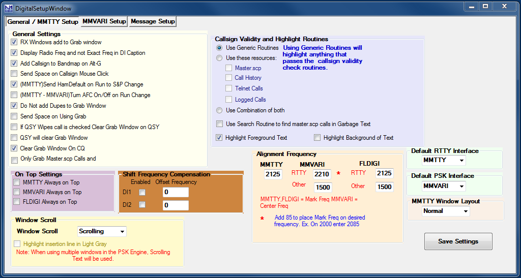
- RX Windows add to Grab window – If this option is checked, callsigns detected in the Additional RX windows will be sent to the Grab window
- Display Radio Freq and not Exact Freq in DI Caption
- Check this option if you are using a radio mode that displays the actual transmitted frequency rather than the suppressed carrier frequency (e.g. FSK RTTY)
- Note that this setup option only affects the frequency that is displayed in the DI window and that is returned by the {RDIGFQ} or {LDIGFQ} macro. To change the frequency that is sent to the Entry window and recorded in the log, see the DI window’s Setup > Turn AutoTRXOffset On/Off menu item
- Add Callsign to Bandmap on Alt+G – (MMTTY and PSK) Option to send callsign from station in callsign field (Alt+O) when doing a grab (Alt+G)
- Send Space on Callsign Mouse Click – Sends a space to advance the entry window cursor after clicking on a call sign
- (MMTTY) Send HamDefault on Run to S&P change – (MMTTY only) Ability to have Ham Default(MMTTY) sent when going from Run to S&P to reset Mark Frequency. Select to enable
- (MMTTY-MMVARI) Turn AFC Off when switching to S&P – (MMTTY and PSK) Ability to Turn AFC Off when going from Run to S&P. Select to enable. Many people when in Running mode will leave the Net Off and turn on AFC to find people coming back to them a little off frequency. So to turn the AFC back off when you go to S&P (without forgetting) this setting comes in handy
- Do Not add Dupes to Grab Window – Setting for adding dupes to Grab window or Not
- Send Space on Using Grab – when doing a grab from the grab window it will also send a space press command to Entry window to advance the cursor
- If QSY Wipes call is checked Clear Grab Window on QSY – If QSY Wipes and Spot call is checked then Clear the Grab window on wipe of callsign.
- QSY will clear Grab Window – Changing frequency will clear the Grab window
- Clear Grab Window On CQ – sending CQ will clear the Grab window
- Only Grab Master.scp Calls and – Will only send calls that are found in Master.scp to the Grab window; if this is left unchecked, anything that passes the callsign validity check routines will be sent to the Grab window
- On Top Settings
- MMTTY always on Top – MMTTY is always in front of all other N1MM logger windows. A restart of N1MM logger is needed to activate this function. Minimizing the N1MM logger program will not minimize the MMTTY engine
- MMVARI always on Top – MMVARI is always in front of all other N1MM logger windows. A restart of N1MM logger is needed to activate this function. Minimizing the N1MM logger program will not minimize the MMVARI engine
- Fldigi always on Top – Fldigi is always in front of all other N1MM logger windows. A restart of N1MM logger is needed to activate this function. Minimizing the N1MM logger program will not minimize the Fldigi engine
- Shift Frequency Compensation – for radios which use/need Shift Frequency Compensation
- Enabled – Select to enable Shift Frequency Compensation
- Offset Frequency – the frequency offset
- Window Scroll
- Window Scroll Type – You can choose between two scrolling behaviors in the RX window:
- Scrolling – New text is always added at the bottom of the RX window. Each time a new line starts, previous text scrolls up one line to make room for the new line at the bottom of the window. The most recent text will always be near the bottom of the window, so you don’t often need to move the mouse away from the bottom two lines or so, but if a newline character is received just as you want to click on something, the text you wish to click on will scroll upward
- Non Scrolling – Previous text does not move when new text is added. The line where text is currently being entered is underlined, and each time a new line starts, the line immediately below the old current line is cleared and it becomes the new current line. If the previous current line was the bottom line of the display, the new current line will be the top line in the display, overwriting whatever was there before. Text does not move after it is entered, which can make it easier to click on than text in a scrolling window, but the most recent text can be anywhere in the window
- Window Scroll Type – You can choose between two scrolling behaviors in the RX window:
- Callsign Validity and Highlight Routines
- Use Generic Routines – the generic routines will highlight anything that passes the check routines (and probably will look like a callsign), using the standard colors for multipliers, QSOs and dupes
- Use these resources: – when selected, only call signs that are found in at least one of the selected resources will be highlighted
- You can select any combination of the Master.scp file, the Call History file, calls that have been spotted on the cluster and appear in the Telnet window, and/or calls that have been logged in this contest
- Use Combination of both – when selected there will be additional highlighting for callsigns that are not found in the selected resources. If the normal highlight is foreground, the background will be changed to yellow; if the normal highlight is background, the text color will be changed to yellow. The yellow color is not configurable
- Use Search routine to find Master.scp in Garbage Text – turn checking for callsigns in garbage text in digital modes on or off. When this is turned on, callsigns that appear in the Master.scp file will be highlighted even if there are garbage characters before and after the call. Note that if a longer callsign is found that contains a callsign in Master.scp, only the callsign from Master.scp will be highlighted; you will have to enter the longer call sign by hand
- Highlight Foreground Text – call sign text will be in the highlight color on the normal background
- Highlight Background of Text – background color surrounding call sign will be changed to the highlight color
- Alignment Frequency – frequency used by the Align button = preferred audio frequency. If you are using FSK RTTY, be sure to set the RTTY alignment frequency corresponding to your radio’s transmit frequency (i.e. set Align frequency to your radio’s Mark frequency in MMTTY, Mark frequency + 85 in MMVARI and Fldigi)
- MMTTY – RTTY alignment frequency. This is the Mark frequency
- MMVARI – Alignment frequencies for MMVARI
- RTTY – RTTY alignment frequency in MMVARI
- NB Add 85 to place MMVARI’s Mark Frequency on desired frequency. Example: For 2125 Mark, enter 2210
- Other – alignment frequency for other modes than RTTY (e.g. PSK)
- RTTY – RTTY alignment frequency in MMVARI
- FLdigi – Alignment frequencies for Fldigi
- RTTY – RTTY alignment frequency in Fldigi
- Other – alignment frequency for other modes than RTTY (e.g. PSK)
- Default RTTY Interface – Select the preferred RTTY interface. Choices are: MMTTY, MMVARI, FLDIGI, TNC or DXP-38
- Default PSK Interface – Select the preferred interface for PSK (and other sound card modes). Choices are MMVARI or FLDIGI
- MMTTY Window Layout
- Normal – The normal size MMTTY window is shown, including waterfall/spectrum, menu bar and control buttons
- Small – The small size MMTTY window is shown, i.e. waterfall/spectrum display only
- Control Menus – Shows waterfall/spectrum plus menu bar
- Control Buttons – Shows waterfall/spectrum plus control buttons
- Save Settings – Save the configuration changes you just made. If you want to back out without saving the changes, click on the X in the upper right corner to close the window; the program will ask you whether you are sure you don’t want to save the changes
Tab: MMVARI Setup
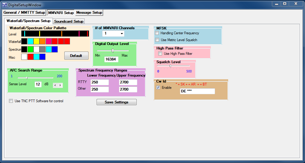
- Waterfall/Spectrum Setup
- Waterfall/Spectrum/Misc Color palette – The colors that make up the color palette can be changed to represent whatever colors you would like. The colors go from the weakest signal on the left to the strongest signal on the right. There is a color palette setting for the Waterfall, Spectrum and for Miscellaneous colors. The Default button changes the colors back to the default colors
- AFC Search Range – This is how far in Hz the interface will track a drifting signal i.e the frequency sweeping width (+/-Hz) for the AFC
- Sense Level – specifies the S/N level (dB) for the wide AFC. When the search range is less than or equal to 50 Hz, the wide AFC does not function. The sense level is applied to all the RX channels
- Digital Output Level – specifies the digital output level in the range of 0 to 32767. The default value is 16384
- Use TNC Software for control – When selected N1MM logger will release the serial port for the TNC so the soundboard in the TNC can have control. When using an external TNC the internal soundboard can be used
- # of MMVARI channels – Number of MMVARI channels to use. Choices are 1, 2, 3 or 4
- Note that if this is set to 1, you have the option to select the Multi-Channel Rx menu item in the MMVARI menu bar, but when it is set to 2, 3 or 4 this option is not available
- MFSK (MFSK only)
- Handling Center Frequency – When selected the center frequency is used for the carrier frequency. When not selected the base tone frequency is used for the carrier frequency
- Use Metric Level Squelch – Select to use the metric level for the squelch. When not selected the S/N level is used for the squelch
- Squelch Level – This level represents the noise level where you would like the interface to start copying signals. 0 indicates an open squelch and everything will be decoded
- High Pass Filter – Select ‘Use High Pass Filter’ to use the internal high pass filter for RX. Although this is unnecessary with most soundcards, it sometimes is effective for eliminating hum in the input audio
- Spectrum Lower Freq – the lower frequency to display when the Spectrum view or Waterfall is active
- Spectrum Upper Freq – the upper frequency to display when the Spectrum view or Waterfall is active
- CW ID
- Enable – If this check box is checked (Enabled) the interface will send the string entered in the field (Enter CWID String) in CW after every transmission. A * will be substituted by SK, + by AR and = by BT
- Save Settings – Save the configuration changes you just made. If you want to back out without saving the changes, click on the X in the upper right corner to close the window
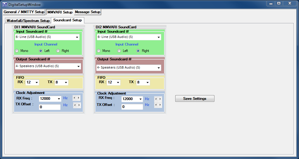
- Soundcard Setup
- DI1/DI2 MMVARI Soundcard
- Input Soundcard # – Select the input soundcard to be used
- Input Channel – Select the input channel. Mono, Left channel or Right channel
- Output Soundcard # – Select the output soundcard to be used)
- FIFO
- RX – specifies the depth of the RX FIFO buffer. Valid values are 4 to 32
- TX – specifies the depth of the TX FIFO buffer. Valid values are 4 to 32
- Clock – Soundcard Clock adjustment
- RX Freq – specifies the sampling rate
- TX Offset – the offset of the TX frequency compared to the RX frequency (some sound cards have an offset between record and playback)
- DI1/DI2 MMVARI Soundcard
- Save Settings – Save the configuration changes you just made. If you want to back out without saving the changes, click on the X in the upper right corner to close the window
Tab: Message Setup
This tab is where you can edit the message buttons that are displayed in the lower part of the DI window. In addition to selecting this tab from the DI Setup window, you can also open this window by right-clicking on one of the buttons.
There are four separate sets of message buttons stored in the database, one for each type of digital interface (MMVARI, MMTTY/2Tone/Fldigi, TNC and DXP38). Before importing, exporting or editing buttons you need to select the particular message set you will be working on.
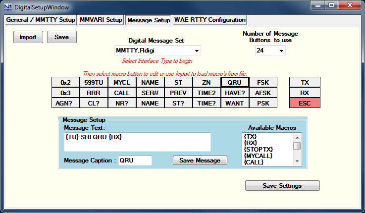
- Import – Once a message set has been selected under Digital Message Set, you can import buttons for that set from a .mc file using the Import button
- Save – You can save the current message buttons in a .mc file in the N1MM Logger+ user files area by using the Save button
- # of Messages – Select the number of message buttons to be displayed in the DI window. You can select 0, 8, 16 or 24
- Digital Message Set –
- Select an interface type from the drop down menu. Choices are:
- MMVARI – messages for the MMVARI interface
- MMTTY,Fldigi – messages for the MMTTY, 2Tone and Fldigi interfaces
- Other – messages for a TNC (such as a PK-232 or KAM)
- Dxp38 – messages for a DXP38
- Click on the message button which is to be updated to transfer that button to the Message Setup area
- The Macro buttons at the right are for TNC interfaces only. Enter the control codes that are needed to switch your TNC between RX and TX
- Only visible when Other is selected
- RX – Receive macro, i.e. the command(s) your TNC needs to put it into transmit. This will become the contents of the {RX} macro
- TX – Transmit macro, i.e. the command(s) your TNC needs to put it back into receive at the end of a message. This will become the contents of the {TX} macro
- ESC – Abort macro, i.e. the command(s) your TNC needs to abort an ongoing message immediately. This will be executed when you press the Escape key
- Select an interface type from the drop down menu. Choices are:
- Message Setup
- Message Text – This is where the text of the message sent by the selected button is displayed and can be edited
- Message Caption – This is where the caption that will appear on that button is displayed and can be edited
- Available Macros – Shows the available macros that can be used in messages. Clicking on a macro will transfer it to the message text area
- Save Message – Save the contents of the Message Text and Message Caption into the selected button
- Save Settings – Save the configuration changes you just made, i.e. the entire set of 24 buttons. If you want to back out without saving the changes, click on the X in the upper right corner to close the window
Tab: DXP-38 Setup
This tab will only show when the DXP-38 TU has been selected under the Digital Modes tab in the Configurer.
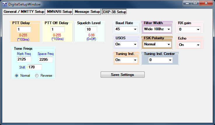
The various settings in this window are for setting up DXP-38 parameters. Consult the DXP-38 manual for detailed instructions on setting them up.
- Save Settings – Save the configuration changes you just made. If you want to back out without saving the changes, click on the X in the upper right corner to close the window
Digital – MMTTY for RTTY support
The MMTTY soundcard interface, which uses the MMTTY engine by Makoto Mori, JE3HHT, is the most popular method for RTTY. Amateurs who use RTTY are indebted to Mori-san for the positive impact MMTTY has had on amateur radio RTTY.
The 2Tone soundcard interface was written by David Wicks, G3YYD, as a replacement for the MMTTY interface in programs like N1MM Logger. It can be substituted for MMTTY as the digital engine used in any of the Logger’s DI windows or Additional RX-only windows. The 2Tone windows are different in appearance from the MMTTY windows, but perform similar functions. These windows are described and documented in pdf files that you download with 2Tone.
MMTTY Windows
When using MMTTY two windows will open.
- the N1MM+ Digital Interface window
- this is the window where received and transmitted text appears, and where the primary operating controls are located
- this window is similar for MMTTY, MMVARI, Fldigi and external Interfaces (TNCs or TUs). See the Digital Interface section
- the MMTTY engine window
- the primary purpose of this window is for its tuning indicators, but you can optionally have it display some of the MMTTY engine controls as well – but unlike the stand-alone MMTTY window, there are no text panes and no macro buttons
- there are four versions which can be selected in the Digital Interface menu under Settings.
- Small version MMTTY engine window (tuning displays only):
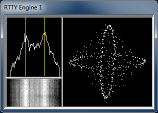
- Normal, or Large version MMTTY engine window, including some control buttons for various MMTTY settings:
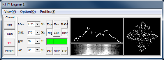
- Control Menus – small window plus the menu bar (View, Option, Profiles)
- Control Buttons – large window minus the menu bar
Note: In the larger windows with the control buttons, there is a TX button. However, this may or may not be operative, depending on whether PTT is controlled from MMTTY (often the case for FSK keying, but rarely for AFSK) or from N1MM+ (such as PTT via Radio Command or from a Winkeyer). In either case, the TX button in the N1MM+ Digital Interface window will always work if the hardware configuration is correct.
Download, Configure and Test MMTTY
Download MMTTY
- Download the installer for the current release of MMTTY here
- At least version 1.64 is needed; version 1.68A or later is recommended
- Run the installer program and install MMTTY to your computer in its own directory
- In Windows 7, 8, 10, 11 and Vista, you must install MMTTY to somewhere other than the Program Files or Program Files(x86) directories (for example, you can create an installation folder such as C:\MMTTY or C:\HamRadio\MMTTY)
- If you are using a standard USB-to-serial adapter for FSK keying, you will probably need to use the EXTFSK plug-in. You can find a link to EXTFSK on the MMTTY download page (near the bottom of the page). Go to the EXTFSK page, then download the ExtFSK106.zip file from the link at the bottom of that page and unzip it into the MMTTY program folder
- Users with high-performance multi-core CPUs (typically a 2.4 GHz i5 or faster Intel based system or 2.4 GHz quad core or faster AMD based system running Windows 7, 8 or 10 or Windows 8) may be able to use EXTFSK64 instead of EXTFSK. EXTFSK64 has improved timing relative to EXTFSK, it supports speeds other than 45.45 baud, and it can be used with LPT ports on 64-bit systems, but its CPU requirements are much greater than those of EXTFSK. See http://www.qsl.net/ja7ude/extfsk/indexe.html for more information and downloads
- When you run MMTTY from inside N1MM Logger+, you will likely want the MMTTY configuration to be different from the configuration used when MMTTY is run stand-alone. MMTTY always saves its configuration data to files within its program folder. Therefore, any copy of MMTTY that is used from within the Logger should be stored in a different folder from the main MMTTY folder. This can be a separate sub-folder in the MMTTY program folder (but not in the C:\Program Files or C:\Program Files(x86) path), or it can be a folder in the N1MM Logger+ user files area, which can be found using the Help > Open Explorer on User Files Directory (e.g., you can create a DigitalEngines sub-folder in the Logger+ user files area and then create separate subfolders in that folder for each copy of MMTTY you wish to run from within the Logger; one for DI-1, one for DI-2, and one for each additional RX-only window you might want to use it in). Then copy only the following files from the main MMTTY program folder into the new folder(s): MMTTY.exe, MMTTY.ini, UserPara.ini, and if you need it for FSK transmitting, Extfsk.dll or Extfsk64.fsk. If you use more than one copy of MMTTY (e.g. for SO2R/SO2V, or for additional RX-only windows), each copy must be installed in its own folder
- The 2Tone engine, which can be used as a drop-in replacement for MMTTY, can be downloaded from the G3YYD folder in the Files area of the N1MMLoggerPlus user group at groups.io, in the form of a zip file containing the 2Tone engine together with documentation for installing and using it. Each copy of 2Tone you plan to run (from DI windows or additional RX-only windows) must be placed in its own folder, the same as described above for MMTTY
Configure MMTTY
FSK KEYING
1. In the N1MM Logger Entry window, select >Config >Ports, Telnet Address, Other >Digital Modes tab
- Select Soundcard as your Interface type
- Select for the selected Digital Interface as MMTTY, Mode FSK
- Select the path to your MMTTY directory (for DI-2 if you are configuring for the second DI window)
2. Still in the Configurer, select the Mode Control tab
- For ‘Mode sent to radio’, in the row labelled RTTY, set the mode to RTTY. This tells the program to put the radio into FSK RTTY mode whenever a band or mode change is commanded from the program.
3. Save and exit the Configurer
- If MMTTY is already loaded you may get an error message about not being able to open port xxxx. This is not a problem at this point; note that you can always re-initialize MMTTY by closing and re-opening the Digital Interface window
4. Open the Digital Interface window (under the Window menu)
- Select the Interface > MMTTY menu item in the DI window
- Select: Option > Setup in the MMTTY window, or use the DI window’s Setup > Setup MMTTY menu item
- Select the TX tab and under PTT, set the serial port that you will be using for FSK keying; if you also use this port in other modes for CW or PTT keying, the Digital and CW/Other check boxes in the Configurer should also be checked for this port, and the DigWndNr in the setup dialog box for that port must indicate which DI window the port will be used with (1 or 2)
- If you are using a control line other than TxD for FSK keying, you must select EXTFSK or EXTFSK64 as the serial port and configure the port and signal line information in the EXTFSK window. If you are using a USB-to-serial adapter, you will most likely also have to select EXTFSK or EXTFSK64 as the serial port and configure the port and signal line information in the EXTFSK window, as most USB-to-serial adapters are not capable of keying FSK RTTY without EXTFSK
- Note that MMTTY’s Radio Command port must be set to NONE; if you use MMTTY’s Radio Command port when running MMTTY stand-alone, you must reconfigure MMTTY not to use this port when it is run from N1MM Logger+
- Select the Misc tab in the MMTTY Setup window and check COM-TxD(FSK) for the Tx Port
- If you are using a USB device to do FSK keying, click on the USB Port button and set the option to C. Limiting Speed
- Select the Sound Card tab (in MMTTY version 1.66G or later) and choose the correct sound card for Reception (the Transmission sound card is not used in FSK) (Note: Users of newer versions of Windows should consult the text box on sound card selection in Windows 7 in the section below on AFSK, as the same issues may apply to sound card selection for reception in FSK.)
- If you are using two copies of MMTTY to decode signals using the two channels of a stereo sound card for different receivers (SO2V) or different radios (SO2R), select the Misc tab again and in the Source pane, select either “Left” or “Right”, depending on which channel you want this copy of MMTTY to decode
- Close the MMTTY Setup dialog
- Close the Digital Interface window to have the Logger and MMTTY save the settings
- Select the TX tab and under PTT, set the serial port that you will be using for FSK keying; if you also use this port in other modes for CW or PTT keying, the Digital and CW/Other check boxes in the Configurer should also be checked for this port, and the DigWndNr in the setup dialog box for that port must indicate which DI window the port will be used with (1 or 2)
Using the RIGblaster Interface for FSK with N1MM/MMTTY
The default for FSK via MMTTY is TxD. You’ll need to change the jumpers when using a RIGblaster. Also, make sure you get MMTTY working as a standalone first. Then you should just be able to specify MMTTY (select Soundcard) in the Digital Interface config in N1MM and it should take off.
AFSK KEYING
1. Open the Configurer (Configure Ports, Telnet Address, Other in the Config menu).
- Select the Digital Modes tab
- Select Soundcard as your Interface type.
- Select for the selected Digital Interface as MMTTY, Mode AFSK
- Select the path to your MMTTY directory (for DI-2 if you are configuring for the second DI window)
- Select the Mode Control tab
- For ‘Mode sent to radio’ in the row labelled RTTY, set the mode to AFSK (for radios that have a dedicated mode for AFSK RTTY) or LSB (for radios that do not have a special AFSK RTTY mode). For most radios, do *not* set it to RTTY; this will put the radio into FSK RTTY mode, which will not work for AFSK. See /manual-supported/supported-radios/#digital-mode-mapping for more information on mode mapping.
- Select the ‘Hardware’ tab
- You can let N1MM Logger+ control PTT, or if you don’t use PTT in other modes and want to have MMTTY control PTT, you can configure MMTTY to control PTT from a serial port. You can time-share a serial port between CW/PTT keying in N1MM Logger+ and PTT from MMTTY; to do this, you must place a check mark under the Digital column beside the port that you are using for the digital port
- If you are using VOX or an external VOX unit like the SignaLink interface to control PTT, you don’t need to configure anything for it in the Logger
- If you have checked the Digital box, click on the Set button and set the Dig Wnd Nr to 1 (or 2 if you are configuring for DI-2)
- If you are using 2Tone in place of MMTTY, do not check the Digital check box for your PTT port
2. Save and exit the Configurer.
3. If you are using an audio codec that is inside the radio, you will need to check the “Internal Radio Codec” check box under the Playback tab in the Logger+ Audio Setup window, which is opened using the Config > Logger+ Audio Setup menu item. If you forget to check this check box, N1MM+ will mute the radio codec when transmitting, which will result in nothing being transmitted.
4. Open the Digital Interface window (under the Window menu)
- Select the Interface > MMTTY menu item in the DI window
- Select: Option > Setup in the MMTTY window, or use the DI window’s Setup > Setup MMTTY menu item
- If you are using 2Tone rather than MMTTY, you will make the configuration settings below in the 2Tone Setup window, which is opened from the 2Tone window
- If you have chosen to have MMTTY control PTT (not applicable with 2Tone), select the TX tab and under PTT, set the serial port that you will be using for PTT. If the port is being time-shared with other modes, this should be the same port that you checked the Digital box for in the Configurer
- Note that MMTTY’s Radio Command port must be set to NONE; if you use MMTTY’s Radio Command port when running MMTTY stand-alone, you must reconfigure MMTTY not to use this port when it is run from N1MM Logger
- Select the Misc tab and check Sound for the Tx Port
- Select the SoundCard tab (in MMTTY version 1.66G) and choose the correct sound card for both Reception and Transmission (users of WIndows 7, Vista and newer versions should read the note below)
- If you are using two copies of MMTTY to decode signals using the two channels of a stereo sound card for different receivers (SO2V) or different radios (SO2R), select the Misc tab again and in the Source pane, select either “Left” or “Right”, depending on which channel you want this copy of MMTTY to decode
- Close the Setup dialog
- Close the Digital Interface window to have the Logger and MMTTY save the settings
Sound Card Selection in Windows 7, 8, 10, 11 and Vista
In earlier versions of Windows, selecting the sound card was relatively straightforward. Windows assigned a number (or two numbers, one for recording=receiving and one for playback=transmitting) to each sound card device when it was installed, and that number could usually be relied upon not to change. Once you had selected the desired sound card in MMTTY, you were finished with the sound card configuration.
Starting with Vista and continuing in Windows 7, 8, 10 and 11, Windows has made life for sound card users more complicated. The list now enumerates each active input or output as a separate device. The list of active inputs or outputs can change dynamically. Plugging or unplugging a cable into one of the jacks on a sound card can create or delete a new entry on the list. Windows power management can turn a USB port off if it has not detected any keyboard activity for some time, causing any inputs or outputs on a USB sound card on that port to be removed from the list. When the computer is restarted or reawakened after hibernating or sleeping, the list may be reconstructed and if there have been changes since the last restart, the order of devices on the list may change. If you are using a radio with a built-in USB codec, turning the radio on or off may add or remove that codec to/from the list. If any of these changes in the list results in a different number being assigned to a device you are using in MMTTY, that device will appear to stop working and you will have to readjust the sound card configuration in MMTTY.
If this happens to you, the way to avoid it is as follows: Immediately before the contest, make sure that every sound card or codec that you plan to use during the period of the contest is turned on and stays on for the duration. Verify your sound card configuration immediately before the contest and then avoid doing anything during the contest that might result in a change to the list. Disable power management features that might result in a USB port you are using being shut off by Windows (these include not only advanced settings including USB selective power suspend under Power Options in the Windows Control Panel, but also power management settings for each Generic USB Hub and USB Root Hub in Device Manager). If you are using the USB codec inside a radio, always turn on the radio before opening the DI window, and close the DI window before turning off the radio; preferably, don’t turn the radio off during the contest. Fortunately not all of these precautions will be necessary in every case, but you should be aware of the possibility just in case.
Another wrinkle introduced in newer versions of Windows is that with some sound cards, the default for the sound card input in the Windows Control Panel may have been set to single channel (mono) instead of two channels (stereo). If you are planning to use both channels of a stereo sound card to decode signals from two receivers (SO2V) or two radios (SO2R), you may need to verify that the default recording format for that sound card input is set to two channels. This is done via the Windows Control Panel (Sound > Recording > select the input you are using and click on Properties > Advanced)
While you are checking the default recording format for number of channels, you will likely also have the choice of setting the sample rate and bit depth. Bit depth is not a problem (16 bits is fine), but the sample rate has become an issue in Windows 7 or later and Vista. The sampling speeds in all applications that are using the same sound card in parallel should be the same, and they should be integer sub-multiples of the hardware sampling rate. The default sampling speed in MMTTY is 11025 Hz, which is suitable for a sound card that is set for CD quality (44100 Hz). However, the sampling speed in 2Tone is 12000 Hz, which is suitable for a sound card that is set for DVD quality (48000 Hz), and it is not user-adjustable. Your best bet is probably to set the sound card’s sampling rate to 48000 Hz (DVD quality), and to change the sampling speed in MMTTY to 12000 Hz (MMTTY Setup window, Misc tab, lower left corner – it’s called “Clock”).
Finally, if at all possible make sure that the sound card you select for digital modes has not been set to be the Windows default sound input or output device. Setting one of the inputs or outputs on a sound card to be the Windows default can disable other inputs or outputs on that sound card, which can make it very difficult to configure those devices in digital mode programs.
Testing MMTTY
MMTTY is also a stand-alone application, so testing can be done outside N1MM Logger+. You can use the originally-installed copy of MMTTY for stand-alone testing. Configuration changes you make in the stand-alone copy will not be applied to the copies that you run from inside the Logger; once you have settled on a setup item in one copy, if you want that same item to apply in other copies you will have to use the Setup window from within each separate copy to change that item.
Dual Receiver/Dual Radio Setup
In a dual-receiver setup (SO2R or SO2V), you may wish to be able to copy two separate RTTY signals (e.g. on two separate bands or two separate frequencies) simultaneously. To do this, you would open two Entry windows (VFO A/Radio 1 and VFO B/Radio 2) and open the Digital Interface window from each Entry window. You can then run MMTTY (or other digital interface engine, such as 2Tone) from each of these DI windows.
The two audio streams from the two receivers can either be decoded by two separate sound cards, or in a single stereo (two-channel) sound card using the left and right channels for the two receivers. In either of these situations, the two copies of MMTTY must have different configurations; in particular, each one must be configured to use a different channel of the sound card, or a different sound card. In the case of a dual radio setup, if you are using FSK on both radios and/or if MMTTY is used to control PTT on both radios, each copy of MMTTY would also have to have access to its own serial port for PTT & FSK. This is also true in SO2V setups in order to enable transmitting from either VFO; even though there is only one FSK keying input to the radio in SO2V, the two DI windows need two separate serial ports for FSK keying, both connected to the same keying input on the radio.
These serial ports are configured in MMTTY. You must set up each copy of MMTTY to use its respective serial port by choosing the relevant serial port in the PTT & FSK Port box under the TX tab in the MMTTY Setup window. If one or both of these ports is time-shared with N1MM Logger+ for CW/PTT keying, then in the Configurer you must indicate this with check marks in the Digital column (Note: in order to check two Digital mode ports in the Configurer, you must be in SO2V or SO2R mode). You must also click on the Set button for each port in the Configurer and set the Dig Wnd Nr to 1 or 2, to indicate which of the two DI windows that serial port will be associated with.
If the two copies of MMTTY are to use different channels of the same sound card, each copy must be configured to use its respective channel on the sound card under the Misc tab in the MMTTY Setup window; or, if they are using different sound cards, each copy must be configured to use its own sound card under the SoundCard tab.
In order to support separate configurations for the two copies of MMTTY, each copy must be located in a separate folder. You can either use the main MMTTY program folder for one copy and a separate subfolder for the other copy, or you can create two subfolders for use by the Logger, leaving the copy in the main MMTTY program folder for stand-alone use. These subfolders must each contain, at a minimum, a copy of the MMTTY.exe file and the UserPara.ini file from the main MMTTY program folder. A copy of MMTTY.ini will be created the first time MMTTY is run from the folder if it was not previously present. If you are using the EXTFSK plugin, you will need a copy of the extfsk.dll file in the folder as well (or the extfsk64.fsk file if you are using EXTFSK64). Other files from the main MMTTY program folder are not used.
The Logger’s DI windows have an additional RX window feature as well. Up to four additional RX-only windows can be invoked from the Setup menus in the two DI windows. They can use either hardware decoders, MMTTY or 2Tone, but the most common use is for separate copies of MMTTY or 2Tone using different decoding algorithms or profiles on the same data stream. Because they are receive-only, these windows do not need access to serial ports and are not configured in the Configurer. However, to be fully useful, although they most likely will share the same sound card and channel with their parent DI window, they do need to have separate setups from the main copy of MMTTY (e.g. to use a different decoding algorithm or profile). Therefore, if you wish to use these additional RX-only windows with MMTTY, you will need to create additional folders, one for each additional window, containing copies of the MMTTY.exe, MMTTY.ini and UserPara.ini files (or if your are using 2Tone in stead of MMTTY, the 2Tone.exe, MMTTY.ini and 2Tone.ini files). These additional folders do not have to be created at the time you first install MMTTY, i.e. you don’t need to do this until you are ready to use the additional RX windows. In Windows 7 or later and Vista, all of these folder must be outside the Program Files and Program Files(x86) paths.
Using MMTTY
- Messages must begin and end with {TX} and {RX}; these macros tell MMTTY to perform PTT switching
- There is no special abort macro needed for use with MMTTY; just using the ESC key will stop transmitting
- The TX and RX buttons in the DI window can be used for free form typing in the TX window pane of the DI window
How to Tune RTTY
- Use the VFO on your radio and dial in the peaks to match the 2 yellow lines on the spectrum
- Click view and the X-Y scope to see a crossed-ellipses tuning display
- If the X-Y display seems to rotate in the wrong direction, open the MMTTY Option > Setup window (or the DI’s Setup > Setup MMTTY menu item), select the Font/Window tab and check (or uncheck) the Reverse rotation button
- Make sure you click the “HAM” button to set MMTTY to the correct mark and shift settings
- The default values for the HAM setting can be changed under the Demodulator tab in the MMTTY Option > Setup window
- It’s better to turn AFC off when you are in a crowded section of the band and manually tune the signals; if you leave AFC on, nearby strong signals may pull the tuning away from the signal you want to copy
- Also in crowded sections it can be helpful to use the built-in notch and bandpass filters
- If you are using AFSK, unless your radio has a specialized mode for AFSK RTTY, the conventional choice with MMTTY is to use LSB on all bands
- If you use USB, make sure you click the “Rev” button in MMTTY
- If you are using FSK, you need to be aware that NET does not work, and that tuning in a received signal by clicking in the waterfall or by allowing AFC to tune in the signal will result in your receive frequency being different from the transmit frequency. The “HAM” button will restore the correct audio frequency in your receive decoder but without retuning the radio. The “Align” button in the DI window can be used to retune your radio so that the received signal is lined up with your radio’s transmit frequency
When Should I Use AFC?
- Use AFC (automatic frequency control) when MMTTY should automatically track the incoming RTTY signal. The best example of this is when you are CQing and want to tune in off-frequency callers
- With AFC and NET both turned on, MMTTY will track the incoming signal and also keep your transmitter frequency locked to the received signal when using AFSK (NET does not work in FSK)
When MMTTY is set to transmit FSK, AFC will work on receive only. When in “Running” mode, you want to keep your TX frequency stable, but with RX AFC set on you can pick up stations who reply a bit off your frequency and copy the exchange without losing your TX spot. Just don’t let the AFC spread get too far from where you’re transmitting.
- A nice option to use is: AFC On/Off with CQ – If set then the AFC will turn on with CQ message or TU messages. This way when Running the AFC is on and during S&P the AFC is off
When Should I Use the NET Option: NET On/Off with Run Change
NET only operates in AFSK. If you are using FSK, your transmit frequency is fixed by your transmitter, and the NET software feature does not work.
- When in ‘Search and Pounce’ mode the program will check the NET option so that once you tune a signal in, you will transmit on the same frequency you are receving him on (Warning: this doesn’t work in FSK)
- When in ‘Running’ mode the program will uncheck the NET option, which allows your receive decoder to follow an off-frequency caller while still leaving your transmit frequency unchanged
Why to Use “Auto Update TRX Offset w/Mark Freq.”
If you are using FSK RTTY, most radios display the actual mark frequency on the tuning dial. A few even do this in AFSK RTTY. If your radio is like this, you don’t need to use this option. The DI window title bar may display an offset frequency (radio dial (+/-) audio), but if this option is turned off the offset frequency will not be logged and you can ignore it.
If you are using AFSK RTTY, especially with the radio in LSB or USB mode, as well as when you are doing a sound card digital mode like PSK (using MMVARI or Fldigi), the radio probably displays the suppressed carrier frequency on its dial. This is different from the mark frequency. If you are using the default mark frequency of 2125 Hz, the radio’s dial display will be 2125 Hz too high (LSB) or too low (USB) as compared with the actual mark frequency. By checking this option, N1MM Logger will perform the correction automatically and display the actual mark frequency in the Entry window and the Bandmap window, as well as in the DI window title bar.
Using MMTTY for 75 baud RTTY
There are some RTTY contests that specify 75 baud (100 wpm) RTTY instead of the usual 45.45 baud (60 wpm) speed. MMTTY can be used for 75 baud RTTY, but there are a few quirks:
- If you use EXTFSK for FSK keying (e.g. via a standard USB-to-serial adapter), you will not be able to use this combination for 75 baud. EXTFSK does not support 75 baud. Instead, you must reconfigure for AFSK
- If your CPU is capable of running EXTFSK64, it can be used in place of EXTFSK. EXTFSK64 supports 75 baud; see http://www.qsl.net/ja7ude/extfsk/indexe.html for information on EXTFSK64
- In the MMTTY Setup window, select the Decode tab, and at the top of the window, for BaudRate select 75
- If you are using MMTTY version 1.68 or newer, in the MMTTY Setup window under the Demodulator tab, in the section labelled HAM Default, UNcheck the “Fixes 45.45 baud” check box
- If you are using an older version of MMTTY, you will need to be aware of the following:
- The pre-version 1.68 MMTTY HAM Default button cannot be used in 75 baud RTTY; if you press HAM, the speed will be reset to 45.45 baud. Besides not pressing the HAM button in the MMTTY window, there are a couple of other setup items you need to take care of:
- In the DI Setup window, under the General/MMTTY Setup tab, make sure the following item is NOT checked:
- (MMTTY)Send HamDefault on Run to S&P Change (if you forget to uncheck this item, you will be switched back to 45.45 baud every time you switch from Run to S&P)
- If you are using FSK with a true serial port or with an interface that supports FSK without using EXTFSK (e.g. a microHAM microKeyer), turn AFC off in the MMTTY window, and make sure the following item in the DI Setup window is NOT checked:
- (MMTTY – MMVARI)Turn AFC On/Off on Run Change (if you forget to uncheck this item, AFC will pull your receive frequency off your transmit frequency and you will be unable to use the HAM button to correct the situation)
- In the DI Window’s Setup menu, UNcheck AFC On/Off with CQ (same reason)
- If you are using AFSK and like to use AFC, you may continue to do so, provided you are careful to ensure that your transmit and receive frequencies stay together. The HAM button is not available to re-align your transmit and receive frequencies. Therefore if you are using AFC, you should have NET on as well, to keep your transmit and receive frequencies together. (Note: NET does not work in FSK)
- In the DI Setup window, under the General/MMTTY Setup tab, make sure the following item is NOT checked:
- The pre-version 1.68 MMTTY HAM Default button cannot be used in 75 baud RTTY; if you press HAM, the speed will be reset to 45.45 baud. Besides not pressing the HAM button in the MMTTY window, there are a couple of other setup items you need to take care of:
- After the 75 baud contest is over, be sure to restore the 45.45 baud speed and any of the other configuration options you changed for 75 baud, in order to restore normal functioning
MMVARI for PSK and Other Modes
The MMVARI Interface
The MMVARI Interface The MMVARI soundcard interface is based on the MMVARI engine by Makoto Mori, JE3HHT.
All modes from the MMVARI engine are supported including bpsk (e.g. PSK31 and PSK63), qpsk-L (LSB), qpsk-U (USB – e.g. QPSK63), also RTTY-L (LSB), RTTY-U (USB), MFSK-L (LSB) and MFSK-U (USB) as well as non-standard modes GMSK (HF), FSK (V/UHF), FSK-W (V/UHF, satellite). The -L and -U variants of some of these modes are there to allow you to choose which sideband you use on the radio. In other words, you are not restricted to using LSB for RTTY and USB for other digital modes; you can choose to use either USB or LSB on the radio, and if you have chosen the correct mode variant in MMVARI, it will adjust the audio tones it uses to correspond to the sideband you have chosen.
MMVARI is capable of using FSK keying for RTTY (selected from the Configurer under the Digital Modes tab, using a specialized version of EXTFSK; this also requires the Logger to be started with the “Run as Administrator” option). Note that the “FSK” mode in the MMVARI mode box is an entirely different mode – it is NOT FSK RTTY.
The MMVARI engine does not have to be installed separately, it is included in the N1MM Logger+ program program/update files and is the default digital engine when loading the digital window for the first time.
The MMVARI Digital Interface Window
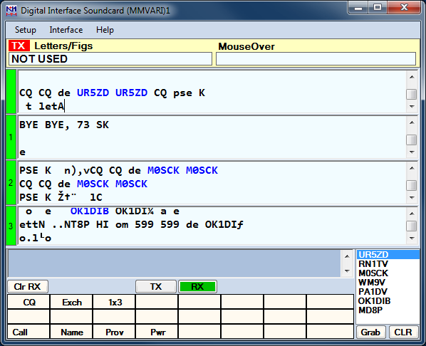
The Digital Interface window when using the MMVARI engine is sub-divided into several areas which will be covered from the top down.
- TX – Indicator to show which DI window the transmit is going to take place from (useful when using two DI windows for SO2R/SO2V)
- Letters/Figs – Shows the text under the mouse in the other case (FIGS/LTRS – RTTY only)
- MouseOver – Shows the text which would be selected where the mouse is positioned over
- Receive Windows – The MMVARI engine supports from 1 to 4 receive windows. The number of receive windows is selected from the DI window’s Setup > Settings menu item in the Digital Settings window under the MMVARI Setup tab (# of MMVARI Channels). All of these windows operate in the same manner and you are able to grab callsigns from any of them and place them into the Entry window. Note that when the # of MMVARI Channels is set to 1, a different method of multiple RX channels becomes available (see The Waterfall or Spectrum Window below)
There is a narrow green pane on the left side of each receive window. By clicking on the green pane you can pause input to the receive window to scroll back through the (last 2000 lines of) text using the scroll bars. When the window is paused the color of the pane will turn yellow. To turn input to the window back on click in the pane again and everything that was to be printed to the window will now enter the window. When the receive window is paused it is possible to copy text in the window.
If you click on a callsign using your mouse it will be put into the callsign field in the Entry window.
Also, whenever a callsign is printed to any of the receive windows followed by a space it will be sent to the callsign grab window for easy movement to the logging window by clicking the Grab button.
You can select any exchange info by single clicking on the sent info. This info will be transfered over to the logger Entry window item by item after the callsign is filled in.
The top receive pane is the window used for making QSOs. Selecting another frequency for this window is done by left clicking in the Waterfall or Spectrum window. Changing the frequency of the other three receive windows is done by moving the numbered marker above the waterfall to the desired location. You can also use the Swap buttons in the lower part of the Waterfall window to exchange the selected window with the top receive window.
- Transmit window – This is a free form typing window. If you click on the TX button the cursor will be placed into this window and whatever is typed will be sent. The size of this window is fixed at 2 lines
- Callsign Textbox and Grab – When a callsign is encountered in one of the receive windows (followed by a space) it will be placed in this textbox and when you press the Grab button it will transfer the callsign over to the main logger window. The grab callsign window holds the last 10 callsigns seen in the RX window. The most current one is at the top and is highlighted. A right click in this box brings up a menu to clear list or selected callsign. Dupe callsigns will not be shown in the grab window
Note: If the callsign in the callsign field in the Entry window is the same as the callsign in the received text, the call in the Entry window does not get placed into the call list.
- Clr RX – Clear all receive windows
- TX – Places the interface into transmit, the transceiver is keyed, and places the cursor into the TX window for input. See the Radio Interfacing section for Parallel and Serial port info on configuring for hardware PTT
- RX – This will place the interface back into receive mode after all the characters in the transmit buffer have been sent. To abort transmit immediately without waiting for remaining characters to be sent, press the Esc key
- Message buttons – These buttons on the Digital Interface are up to 24 extra preprogrammed messages. Configuring these macros is done in the Digital Interface window under ‘Setup, Settings’ (Message Setup tab), or by right clicking on one of the buttons, which brings up the Digital Setup window. The button widths dynamically adjust in relation to the width of the DI window. If the caption for a button is too long to fit on the button, the button will appear blank; you can cause the caption to appear by making the window wider, or you can edit the caption to make it shorter so it will fit
- Grab – Transfer the selected callsign in the callsign text box to the callsign field on the main logger window. The cursor advances to the exchange box ready to accept the exchange when you click on it
- CLR – Clears the grab window
The MMVARI Waterfall or Spectrum Window
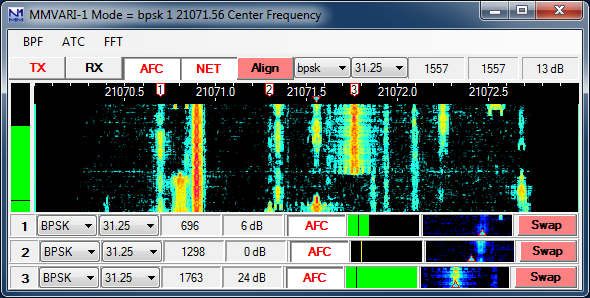
The MMVARI digital engine window – This window uses the MMVARI control from Makoto Mori, JE3HHT. Across the top the title bar shows either the offset frequency (radio (+/-) audio) or the radio’s dial frequency, depending on a setup option. As you tune your radio this will update and the numbers will change.
The screen shot here shows the window with four receive channels selected in the Digital Setup. There are cursors corresponding to each of the receive windows. The inverted triangle cursor, filled in in light blue, is for the main receive window. If NET is on, this is also your transmit frequency. If NET is off, there will be another inverted triangle filled in in dark blue indicating your transmit frequency. If you have more than one receive window enabled, a cursor with a number in it (1, 2, …) corresponds to each additional receive window. To change frequency for the main receive window you can place your mouse pointer over a signal trace and click with your left mouse button. To change frequency for one of the other receive windows, you can click on the numbered cursor and drag it to the desired location in the waterfall.
Note that if you are using FSK keying in RTTY, MMVARI has no control over your transmit frequency. Your transmit frequency in FSK RTTY is fixed by the radio. Therefore, moving the dark blue transmit indicator does not change your actual transmit frequency in FSK RTTY. Likewise, the NET function is inoperative in FSK RTTY.
- Buttons above the waterfall
- TX – Start the transmission, the transceiver is keyed and places the cursor into the TX window for input. See the Radio Interfacing section for Parallel and Serial port info for TX/RX switching (PTT)
- RX – Stops the transmission, the transceiver changes back to receive after all the characters in the transmit buffer have been sent. To abort immediately, press the Esc key
- AFC – Turns AFC on or off. Selected (white) means AFC on (Note: This button is greyed out and disabled when the Multi-Channel RX browser feature is enabled)
- NET – Turns NET on or off. Selected (white) means NET on. When NET is on the TX frequency follows the RX frequency (this function is inoperative in FSK RTTY)
- Align – This is used to move the signal under the receive indicator to the Alignment Frequency set up in the Digital Setup window. This can be used in most sound card modes to center the received signal in your filter bandpass, and in FSK RTTY it is used to align the received signal with your transmitter’s signal
Example: Suppose the center of the filter pass band is 2200 Hz. When clicking on a signal at about 1400 Hz the signal may be difficult to copy unless you are using wide filters. To move the signal to the center of your filter bandpass, click Align and the rig shifts and the spectrum frequency shifts and places the station on the frequency that was initialized in the Digital Setup window in the Alignment Frequency area. This allows you to narrow your filter bandwidth around the selected signal. If you are using FSK keying for RTTY and if your receive frequency is not exactly on the center frequency of your radio’s mark/space tone pair (e.g. 2210 Hz for the standard 2125/2295 “high” tone pair), then you can use the Align button to retune your radio so your receive and transmit frequencies will be aligned correctly.
- Mode selection – Select the mode to use by clicking on this button. The Speed selections are mode dependent. Selections are:
- GMSK – MBCS experiment (HF) – Possible speed selections: 31.25, 62.5, 125, 250
- not used for contests
- FSK – MBCS experiment (V/UHF) – Possible speed selections: 31.25, 62.5, 125, 250
- not used for contests
- Do not confuse this mode with FSK RTTY – MMVARI’s “FSK” mode is not FSK RTTY. MMVARI in N1MM Logger+ does support FSK RTTY, but this can only be selected from the Configurer, not from the MMVARI window
- FSK-W – MBCS experiment (V/UHF, satellite) – Possible speed selections: 31.25, 62.5, 125, 250
- not used for contests
- BPSK – MBCS experiment (HF) – Possible speed selections: 31.25, 62.5, 125, 250
- for contesting purposes, BPSK and bpsk are equivalent
- bpsk – Standard BPSK (e.g. PSK31) – Possible speed selections: 31.25, 62.5, 125, 250
- rtty-L – BAUDOT RTTY (LSB) – Possible speed selections: 45.45, 50, 56, 75, 100, 110, 150, 200
- rtty-U – BAUDOT RTTY (USB) – Possible speed selections: 45.45, 50, 56, 75, 100, 110, 150, 200
- You may choose either AFSK or FSK keying method for RTTY in the Configurer under the Digital Modes tab
- mfsk-L – MFSK (LSB) – Possible speed selections: 15.625, 31.25
- mfsk-U – MFSK (USB) – Possible speed selections: 15.625, 31.25
- qpsk-L – QPSK (LSB) – Possible speed selections: 31.25, 62.5, 125, 250
- qpsk-U – QPSK (USB) (e.g. QPSK63)- Possible speed selections: 31.25, 62.5, 125, 250
- GMSK – MBCS experiment (HF) – Possible speed selections: 31.25, 62.5, 125, 250
- Speed selection – Select the speed to use in bps by clicking on this button. The speed to select is mode dependent as described above
- Main Channel receive frequency – audio frequency
- In RTTY, MMVARI displays the center frequency, not the mark frequency as displayed in MMTTY
- Main Channel transmit frequency – audio frequency
- Main Channel S/N reading
- The Waterfall or Spectrum Display
- At the top of the waterfall offset frequency (radio (+/-) audio) labels and tick marks are displayed
- Receive channel markers
- Top markers (tag cursors)
- 1,2,… – frequency receive channel 1,2,…
- N – indicates a notch filter
- The light blue colored marker (inverted triangle on the waterfall) indicates the main RX frequency
- The dark blue colored marker (waterfall) indicates the TX frequency if it is different from the main RX frequency (only possible if NET is off)
- Top markers (tag cursors)
- Mouse key clicking
- Left mouse key clicking – single clicking in the waterfall will change the main RX frequency
- Right mouse key clicking – the audio frequency at the point clicked on will be shown. Also a menu will show:
- Set notch on here – adds a new notch filter on the selected frequency indicated by a N in a yellow area. Multiple notches can be set; you can clear an individual notch by right-clicking on the N
- Delete all notches – all set notches will be removed
- Set TX Carrier on here – can be used to set the TX frequency (with NET off)
- Turn Off Bandpass Filter – Turns the BPF off
- RX 1 (2,3) Freq Here – can be used to set the RX 1, 2, or 3 frequency here (only if the # of MMVARI Channels is greater than 1)
The left vertical indicator shows the signal level meter (green) and the squelch level (yellow line). Biy clicking on it the squelch level can be changed.
- Receive channels below the waterfall
- If you have chosen to use more than one MMVARI channel, below the waterfall the additional receive channels will be shown. The number of additional channels below the main waterfall is one less than the total number of MMVARI Channels set, i.e. there can be up to three additional channels (up to four MMVARI channels in total – to display more than four channels, see the Multi-Channel RX feature below)
- Mode – Select the mode to use for this receive channel
- Speed – Select the speed to use for this receive channel
- Receive channel frequency
- Receive channel S/N value
- AFC – Turns AFC on or off for the selected channel. Selected (white) means AFC on
- Squelch indicator – The squelch can be adjusted by dragging the line indicator to where you want it and turning off the squelch by dragging it all the way left
- Miniature waterfall display – shows within 500 hz of the signal that that channel is on. You can click anyplace in this miniature waterfall or drag the indicator to where you want it
- Swap – Exchanges this receive window with the main receive window. While working one station, you can dial the second station in via a second receive window and after you finish the first contact just hit swap button and then call the other station. See below for an alternative method of multi-channel receive
- Menu at the Top
- BPF – Used to enable/disable an internal audio Band Pass Filter. The BPF filter has steep skirts and 80db of rejection outside the bandpass. However, because it is in the sound card and not in the radio, it has no effect on unwanted signals inside the radio, i.e. a strong unwanted signal inside the radio’s IF filter bandpass can still trigger the radio’s AGC and cause gain blocking, even though the signal has been rejected in the sound card by the BPF. You can only prevent this by selecting narrow filters in your radio
- Enable/Disable BPF – turns BPF on or off
- Wide 1000 Hz, Middle 500 Hz, Narrow 250 Hz, Ultra Narrow 100 Hz, Custom – filter bandwidth settings (grayed out when the BPF is disabled)
- To set Custom width after enabling the BPF, left click in the waterfall where you want the BPF bandpass to start. Drag your mouse with the left button held down and release it where you want the BPF bandpass to end. The waterfall display will immediately relect the chosen Bandpass. This makes it simple to eliminate an offending station on the fly
- The minimum width of the BPF that can be set is 100 Hz
- The BPF can be turned off by selecting Disable BPF on the BPF menu or by right-clicking in the waterfall and selecting Turn off bandpass filter
- The BPF settings are retained when you close and reopen the digital engine window
- ATC – Used to turn Automatic Timing Control (ATC) on or off. It is recommended to keep ATC on all the time for better signal decoding
- when RTTY is selected ATC is always off
- in MFSK mode ATC is always on
- FFT – FFT is Fast Fourier Transform, which is a method of extracting the spectrum out of a waveform. That is the basic tool that gives the waterfall and spectrum scope displays
- FFT Type – Select the FFT display method. Selections are: Spectrum, Waterfall, Sync or Wave Input
- FFT Width – Select the display width (frequency range). Selections are: 250 Hz, 500 Hz, 1000 Hz, 2000 Hz, 3000 Hz or User Defined. User Defined width is set in the Digital Setup window
- FFT Scale – Select the vertical scale to use. Selections are: 100 dB, 60 dB, Square Amplitude
- Waterfall AGC – Turn the waterfall AGC on or off
- Align after Left Click – Automates the Align process. Any time a signal is clicked on in the waterfall, an automatic Align operation is performed to re-center the audio frequency on the Alignment Frequency you have selected in the Digital Setup window
- SHIFT – Shift selections. The choices are 170 Hz, 200 Hz, 23 Hz or User Defined
- Only in RTTY-L, RTTY-U and GMSK
- RTTY Demodulator – select either IIR or FFT decoder. Depending on conditions, one may decode better than the other
- Only in RTTY-L and RTTY-U
- BPF – Used to enable/disable an internal audio Band Pass Filter. The BPF filter has steep skirts and 80db of rejection outside the bandpass. However, because it is in the sound card and not in the radio, it has no effect on unwanted signals inside the radio, i.e. a strong unwanted signal inside the radio’s IF filter bandpass can still trigger the radio’s AGC and cause gain blocking, even though the signal has been rejected in the sound card by the BPF. You can only prevent this by selecting narrow filters in your radio
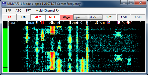
- Multi-Channel Rx – This feature is only available when the # of MMVARI Channels in the Digital Setup window under the MMVARI Setup tab is set to 1. It is an alternative method of receiving multiple signals simultaneously with MMVARI
- Enable Multi Channel Browser – turns this feature on
- When the Multi-Channel RX feature is turned on, there will be several numbered tag cursors at the top of the waterfall, and a separate browser window will open (see below). The number of channels is user-selectable (from 2 to 24)
- Each line in the browser window shows text decoded under the corresponding numbered cursor
- There is only one RX pane in the Digital Interface window, which displays text from the main RX signal under the light blue inverted triangle cursor
- You can move the main RX cursor to the position of any of the numbered tag cursors simply by clicking in the corresponding small text window
- You can use this feature to keep track of several separate signals being received. You can work each one in turn by clicking in the corresponding numbered text window to move the main RX/TX frequency (with NET on) to each numbered cursor position in turn (if NET is off, or you are using FSK RTTY, clicking in the text window only moves the RX frequency but not the TX frequency)
- Open/Close Multi Channel Brower – turns the feature on or off (only visible after it has been enabled)
- Set Number of RX Channels – you can select from 2 to 24 channels to display in the browser window
- Set AFC Search Level – Used to set the signal level (S/N ratio) used to determine whether a signal is strong enough to activate the AFC and cause the RX frequency to move to it (can be set from 1 to 20 dB)
- Set AFC Search Range – Each extra RX channel has AFC (automatic frequency control) which moves the cursor to keep it centered on a signal if the frequency changes slightly. This menu item is used to set the frequency range over which this feature operates (can be set from 100 to 500 Hz)
- Set Spectrum Search Frequencies – Allows you to set the lower and upper limits for the browser channels. The lower limit can be 250 Hz or higher, and the upper limit can be 2700 Hz or lower
- Turn Channel Markers On – If unchecked, channel markers will not be displayed
- Show Audio Frequency Only – if checked, audio frequencies will be displayed instead of RF frequencies
- Enable Multi Channel Browser – turns this feature on
The Multi-Channel RX method allows you to keep track of more channels (max 24) than the older # of MMVARI Channels method (max 4) that you set up from the Digital Setup window. The memory for each channel is limited to 80 characters. You can click on callsigns in the callsign column of the browser window in order to transfer them to the Entry window, or in Dxpedition mode (see below), you can click on a callsign in the browser window in either the decoded stream or the callsign column to: move the RX cursor (and if NET is on, the TX cursor) to that channel, transfer the callsign to the Entry window, and transfer the last 80 characters decoded in that channel into the main RX window. All channels in the browser in this method will be in the same mode. In RTTY, clicking on the channel marker for a channel switches between normal and reverse decoding in that channel. (For another way to do multiple receive in PSK only, you can also try the PSK Browser in Fldigi).
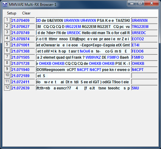
Browser window in multi-channel RX
- Setup menu
- Set On Top – check this if you want to ensure that the browser window is always on top of other windows
- Set AFC Width – set the frequency range for AFC in each browser channel
- Set AFC Level – set the signal level that activates AFC
- Set Squelch Level – set the squelch level in the browser
- Set Channel Background Color – set the background color for the text in the browser window
- Set Channel Text Color – set the color for text in the browser window
- Set Channel Highlight Color – set the color for the highlighted channel
- Dxpedition mode – turns Dxpedition mode on or off
- With Dxpedition mode off, clicking on a channel in the browser moves the main RX cursor to the frequency of that channel. If NET is on, the TX cursor also moves to the same frequency
- With Dxpedition mode on and NET off, clicking on a callsign in either the text stream or the callsign box in a browser channel:
- Moves the main RX cursor to the frequency of that channel, leaving the TX cursor where it was
- Transfers the last 80 characters from that channel into the main RX window
- Transfers the callsign into the Entry window
- Can be used in a Dxpedition situation where your TX frequency is fixed and you want to work stations anywhere in your receive range
- With Dxpedition mode on and NET on (this is not possible in FSK RTTY), clicking on a callsign in either the text stream or the callsign box in a browser channel:
- Moves the main RX and TX cursors to the frequency of that channel
- Transfers the last 80 characters from that channel into the main RX window
- Transfers the callsign into the Entry window
- Can be used for normal S&P operating. After switching to the frequency of the selected channel, you can click on the Align button to center that channel in your receiver’s filter bandpass
- Clear menu – clears the browser window
Setting Up the Digital Interface
The setup dialog is for both MMTTY and MMVARI, this means that some settings are only for MMVARI, MMTTY or both. When selecting ‘Setup | Settings’ in the Digital Interface window a dialog wil be shown which is both for MMTTY and MMVARI. Please check the setup information in the Digital Setup chapter.
MMVARI Example
- Select ‘Window > Digital Interface’ in the Entry window to open the Digital Interface and the Waterfall/Spectrum window. The Digital Interface dialog can be positioned and resized on your monitor as desired
- Left clicking on a call will grab the callsign. Right clicking on the RX and TX window will pop a menu (S&P mode) or send the Exchange function key in Running mode, depending on your choice for te Rt. Click option in the DI Window’s menu
- Pressing Insert will Grab the highlighted call and sends His call followed by the Exchange button
- Double clicking on a callsign in the callsign box from the Digital Interface sends that call to the Entry window
- A callsign is automatically highlighted if recognized by the program. For that to happen it needs to have a space before and a space after the callsign
Digital – Fldigi for Sound Card Modes
The Fldigi interface
The Fldigi sound card interface is based on the fldigi code by Dave Freese, W1HKJ.
Fldigi supports a wide variety of digital modes, including not only AFSK RTTY and PSK, but also other less common modes such as MFSK, MT63, Olivia, Throb, etc.
Fldigi is a stand alone application, so you can also use it separately from N1MM Logger. Note that the configurations for Fldigi stand-alone and within the Logger are separate, i.e. changes made to the stand-alone configuration will not be applied to the configuration within the Logger, and vice versa.
Fldigi does not support keying outputs on serial or parallel ports, as used by N1MM Logger for CW and FSK keying. Fldigi can be used from the Logger for AFSK RTTY or for PSK31 or other digital modes, but not for transmitting RTTY using FSK unless you use an external hardware circuit to convert audio output from Fldigi to an on-off keying signal for FSK. It can also be used as a CW receive-only decoder, but not for transmitting CW. For transmitting CW, use one of the CW interfacing methods detailed in the “Basic Interfacing – Radio, CW, PTT” chapter. You must not check the Digital check box on a port that will be used for CW keying while the DI window or the CW Reader window is open.
Download and Configure Fldigi
Download Fldigi
- Download the current release of fldigi from the W1HKJ website at http://www.w1hkj.com/ . You can find a copy of the full installer for the current version of fldigi at that website. This file is a self-extracting executable, similar to the N1MM Logger installer. Download the installer file to a temporary folder and then execute it. It is recommended that you install fldigi in its own program folder and not in the N1MM Logger+ program folder. By default, the installer will install fldigi to C:\Program Files\Fldigi-x.xx.xx\, where x.xx.xx is the fldigi version number.
- If you are using Windows Vista, 7, or later, and you want to run fldigi from inside N1MM Logger+, you must use a copy of fldigi.exe that is located in its own folder outside the Program Files (or Program Files(x86)) folder. You can, for example, create a folder for fldigi inside your N1MM Logger+ user files area, then make a copy of fldigi.exe from the original installation location and copy it into the new folder. The only file you need to copy is the exe file; it will create whatever other files it needs the first time it is run.
Fldigi Initial Configuration
After fldigi has been downloaded and installed, open the Configurer and set up the path to fldigi.exe under the Digital Modes tab. After closing the Configurer, choose a contest in N1MM Logger that supports digital modes, select the Window > Digital Interface menu item from the Entry window, and then in the Digital Interface window, select the Interface > Fldigi menu item.
When you first open the fldigi interface from the Logger, and also any time you install fldigi into a different location, such as separate locations for the two digital interface windows or for the DI window and the CW Reader window, you will be prompted to fill in some configuration information by the fldigi configuration wizard, as follows:
- Operator information – You do not need to fill in any of this information; N1MM Logger+ handles logging and all related information
- Audio devices – Under the Devices tab, check the PortAudio box and select the sound card input and output you are using for Capture and Playback. Click Next
- Transceiver control – In fldigi version 4.1.02 and newer, do not select any method of rig control in fldigi. In older versions, select the XML-RPC tab, check the Use XML-RPC Program box, and click the Initialize button. Do NOT select flrig, RigCAT, Hamlib, or MemMap for rig control; none of those will work with N1MM Logger+
- You can let N1MM Logger handle PTT, in which case you do not need to configure PTT in fldigi. This is the simplest (recommended) configuration. However, if you do not use PTT in other modes and you want to use hardware PTT controlled by fldigi, you can select the Hardware PTT tab, check the Use separate serial port PTT checkbox, select the appropriate COM port in the Device: window, and check either Use RTS or Use DTR, depending on which one your hardware setup uses. If the label on the Initialize button is red, click on the button. Note that a COM port that is used by fldigi cannot be used simultaneously by the Logger for other purposes. If you are time-sharing a serial port between fldigi in digital modes (not including CW) and the Logger in CW or SSB, check the Digital check box beside the COM port in the Configurer to ensure that the Logger will not try to use this port while the Digital Interface is open
- If you intend to use fldigi as a receive-only CW decoder, be aware that you cannot use fldigi to transmit CW. Also, you cannot control PTT from fldigi on the same port that N1MM Logger+ uses for CW keying; do not check the Digital check box beside this port, and do not configure it within fldigi as a PTT port
- Click Finish
The fldigi configuration wizard does not automatically save its settings. After you have exited the configuration wizard and the main fldigi interface window has opened, you must save the configuration settings using the fldigi Configure > Save Config menu item. If you don’t do this, then every time you open the fldigi window you will have to go through the configuration wizard steps again. Similarly, any time you make a subsequent change to the fldigi configuration you must explicitly save the new configuration if you want the change to be remembered.
Newer versions of fldigi may default to requiring confirmation from the user before you shut them down. If that shutdown is initiated by shutting down N1MM Logger+, instead of by shutting down the DI windows and engines first, this can result in fldigi continuing to run after the Logger has shut down. This will cause problems the next time you start up the Logger. To prevent this from happening, you need to make a change in the fldigi configuration file. In each folder that fldigi is run from, find the file called fldigi_def.xml. (Note: this file is created the first time fldigi is run from this location, i.e. it will not exist until after you have run that copy of fldigi at least once). Right-click on the file name, select Open with… and then select Notepad or Wordpad as the program to open the file with. Look for a line that reads <CONFIRMEXIT>0</CONFIRMEXIT> or <CONFIRMEXIT>1</CONFIRMEXIT>. If you see a 1 between the two keywords, change it to a 0 and save the file. Repeat this for each and every copy of fldigi you use from within N1MM Logger+ (DI1, DI2, additional RX-only digital windows, CW Reader 1 and/or CW Reader 2).
The Fldigi Interface Window
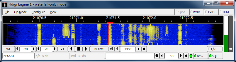
- Menu
- File
- Exit – closes the Fldigi window
- Op Mode
- CW – This configures Fldigi to decode CW (receive-only)
- PSK – select BPSK-31 for normal PSK31, BPSK-63 for PSK63, etc.
- RTTY – select RTTY-45 for normal 45 baud AFSK RTTY
- Other selections can be used for other modes – see the fldigi help for details
- Configure
- Waterfall – under the Display tab, you can select whether to show audio or RF frequencies in the scale at the top of the waterfall, and whether to display transmitted as well as received signals
- Rig control – you can use the Hardware PTT tab to change the PTT settings for a separate hardware PTT port
- Sound card – you can select the sound card to be used by Fldigi under the Devices tab
- Modems – this is where you make configuration changes that apply to specific modes only (e.g. PSK-specific changes, or RTTY-specific changes)
- Save Config – use this to save the new configuration any time you make changes
- View
- PSK Browser – opens a browser window that can display up to 30 signals within the waterfall simultaneously (PSK only). To configure this browser window, use Fldigi’s Configure > Modems > PSK > Viewer configuration window to set the number of channels, the starting (lowest) audio frequency (channel separation is 100 Hz), and various other parameters
- File
Most Fldigi menu items not mentioned above are either not used by N1MM Logger, or perform advanced functions that are not needed for basic operation. See the fldigi help at the W1HKJ web site for more details (there is a link to the Fldigi-Help page from the download page at
http://www.w1hkj.com/download.html).
Note also that when the Fldigi engine is selected, additional buttons appear in the Logger’s Digital Interface window:
- Align – for retuning the radio so that the desired signal is aligned on a pre-configured frequency
- Lock – to lock the transmit frequency at the present position in the waterfall while allowing the receive frequency to vary (for operating split)
- Rev – in sideband-sensitive modes like RTTY, reverses the tones
- Unlike the other digital engines used in the Logger, Fldigi assumes the rig will be in USB for RTTY. If you are using LSB, you will need to use the Rev button to tell Fldigi to reverse the tones. If you have tuned in a signal but all you see in the receive text window is garble, try clicking the Rev button once or in some cases, twice (sometimes you may find it necessary to toggle the Rev state off and back on to get it to “take”)
Note that older versions of Fldigi only use the left channel on input; for that reason, in most SO2V installations these older versions of Fldigi can only be used from Entry Window 1. Starting with Fldigi version 3.22.06, Fldigi is now capable of using either sound card channel for input. In any copy of Fldigi that you want to use with the right channel of the sound card, use the Configure > Sound Card menu item in the Fldigi window to open the Fldigi configuration window. Select the Right channel tab, and near the bottom under Receive Usage, check the Reverse Left/Right channels check box to switch Fldigi to use the right channel on RX. Click on Save to save the configuration change, and then close the configuration window.
Digital – External TNC Support
The Digital Interface will not only work with MMTTY, MMVARI and external TNC’s like the PK232, HAL DXP38 but with ANY TNC.
This is because (with the special-case exception of the HL DXP-38) the commands for the TNC are not hard coded into the program. This has to be done by the user of the program.
Information about the following external TNCs can be found below but as already stated ANY TNC that uses serial communication can be used with N1MM Logger.
The Digital Interface
The Digital Interface can be used with any external TNC.
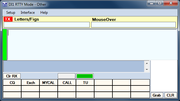
Using a TNC will show an interface like the one above.
Setting Up the TNC in the Configurer
- Start the N1MM Logger application
- On the Logger Main Window select >Config >Configure Ports, Telnet Address, Other >Digital Modes tab
- In Digital Setup
- Choose Other for Interface (for any TNC except for the HAL DXP-38; for the DXP-38, see separate instructions below)
- Set other parameters accordingly (Example settings: Com 4 ,9600 ,8 ,N ,1, RST-Xon)
- Save the configuration [OK]
- Load the Digital Interface from the Window menu
- Program the RX, TX and Abort macros by opening the Digital Setup window (Setup > Settings menu item in the DI window), selecting the Macro Setup tab, selecting the “Other” digital macro set, and then right-clicking on each of the TX, RX and Esc buttons at the right side of the window and programming them with the appropriate codes to put your TNC into transmit, to put it into receive at the end of a message, and to abort a message, respectively. Once you have done this, the {TX} and {RX} macros will work in function-key messages and the other DI button messages, and the Esc key can be used at any time to abort a transmission.
Make sure your interface is set to copy RTTY at 45 baud and 170 Hz shift. If necessary, you can type the TNC command(s) for this in the transmit window so it will be sent to the TNC, or (better) you can program it into one of the DI message buttons.
Test Your External TNC
- Test stand-alone
- See the separate sections for the PK-232, KAM, HAL etc. If your TNC is not mentioned please set it up like the other mentioned TNC’s
Make sure your radio and TNC work on your computer’s serial port by testing them with an existing terminal program. Connect your TNC/Radio into your computers serial port. The Hyperterm terminal program is included with Windows and works well. Make sure you note all COM port parameters. You should be able to tune in a RTTY signal and print it using the Hyperterm program. The Windows Hyperterm is geared toward modem communications and is not especially intuitive for direct COM port use. As stated previously, you can use any number of terminal emulator programs. For example, the Tera Term Pro 3.1.3 by Ayera Technologies is a small, open source, free terminal emulator that is available for download.
The interface has been tested with the three mentioned TNC’s below and works fine with them. Any other TNC should also work as long as you place the right commands for that TNC in the macros.
Additional Macros for the External TNC Interface
The Digital Interface will accept all of the Macro keywords that can be used in the Packet window and other places in the Logger and will also accept the following: {CTRL-A} – {CTRL-Z}, {ESC}, {ENTER}.
These macro keywords can be used in any of the DI message buttons or the Logger function keys in the Entry window.
The TX window will accept all control key commands except for the Esc key, which must be sent as a Shift+Escape combination.
Remember that when setting up a message key that is not a TNC command you will need to include the {TX} macro (or the equivalent TNC command) to key the TNC before it sends. If a message does not start with the {TX} macro, your TNC will think it is a command being sent to it instead of message text, and it will not know how to process it. Before using the {TX} and {RX} macros in messages, you need to initialize them with the correct commands for your TNC, by opening the Digital Setup window, selecting the Macro Setup tab, selecting the “Other” Digital Macro Set, and then programming the TX, RX and Esc buttons with the correct command sequences for your TNC.
To use free form typing in the TX window you need to first key your TNC (e.g. using the TX button after it has been programmed correctly for your TNC). Click the TX button to start transmitting and then click in the TX window. Whatever you type in the TX window now will be sent out. After you have finished typing, click on the RX button to return to receive mode.
HAL DXP38 Setup
The HAL DXP-38 is supported as one of the possible interfaces. Setup for the DXP-38 is different from setup for other TNCs.
There is a selection for the DXP-38 interface type in the Configurer under the Digital Modes tab, TU type.
Hardware Setup
It is a good idea to get the DXP38 running with WF1B, HAL or another known software package before trying to set it up for the first time in N1MM Logger. Doing this eliminates the need to troubleshoot both hardware and software simultaneously when configuring N1MM Logger. Hardware setup:
- Connect the PTT and FSK lines to the rig
- Connect the COM port (1 for HAL software) to the TNC
- Connect audio input to the DXP-38
- Connect the power
- Connect AFSK output to the rig (AFSK only)
- Consult the DXP-38 manuals for the details. The rig must be setto FSK RTTY (LSB) or LSB for AFSK
Software Setup in N1MM Logger
Port configuration – The COM port used for the DXP38 port should have a check mark in the Digital check box in the Configurer.
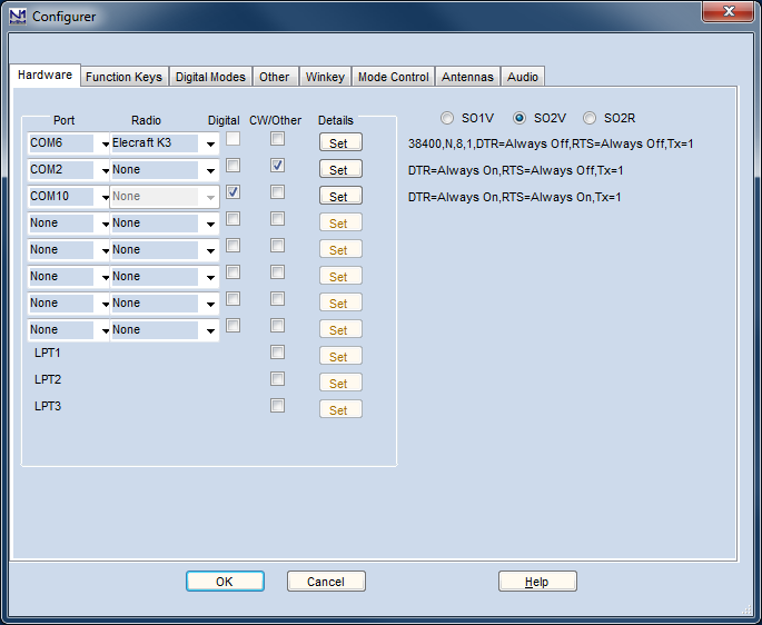
Under the port settings (Set button), DTR/RTS should be set to Always On. Set the DigWNdNr to the digital window number that the DXP38 will be used with (1 or 2, for DI window #1 or #2).
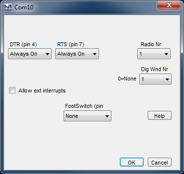
Digital configuration – In the Configurer under the Digital Modes tab, in the left side for the digital interface window that the DXP38 will be used with (Digital Interface 1 or 2), the port settings should be 9600 baud, N,8,1 and no handshaking:
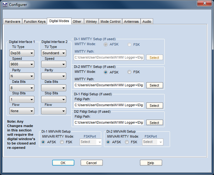
Command macros to control the DXP38
Most of the useful DXP38 features can be controlled from the DI Setup window under the Dxp-38 Setup tab. However, you may also use DXP38 macros in the DI window buttons (but NOT in the Entry window function keys). To program one or more of these buttons, you can right-click on one of the buttons to open the editing screen. The HAL command set is documented in the DSP4100 technical documentation at the HAL website. The HAL macros are in the form of two hexadecimal bytes, the first of which is a hex 80. To program a command whose second byte is xy (where x and y are hexadecimal digits), include a macro in the form {H80xy} in the message button. You miust follow this exact template: the macro is surrounded by curly braces and starts with an H, followed by four hexadecimal digits (8, 0 and the two digits corresponding to the desired HAL command). Once you have edited one of more of the message buttons, you can save the entire file in the Dxp38 macro button set using the Save Macros button in the edit window.
RTTY messages
Your contesting and other RTTY messages can be either in the Entry window function keys (F1-F12, e.g. for use from the keyboard or with ESM) or in some of the DI window buttons (for auxiliary messages that are only used occasionally, by clicking on them with the mouse). These messages work the same way with the DXP38 as for other digital interfaces. Start each message with {TX} and end it with {RX}. Note that message buttons that are programmed in the DI window set with Dxp38 selected as the interface type will be stored in the Dxp38 macro set, i.e. they will be saved separately from message buttons that you set up for MMTTY or for MMVARI.
First time startup
- Start up N1MM logger first
- After the program loads, make sure focus is on the TNC received text screen. Then turn on the DXP38. If the data link is OK , an @ will be printed on the screen. It takes about 20-30 seconds for the DXP to initialize after the @ appears in the RX window.
- Subsequent startups
- Turn on the DXP38. Start N1MM logger. After the DXP38 initializes, you should see a text rendition of the initialization process on the screen. The following screen shot is from the classic (pre-Logger+) version of the Logger, so yours may look slightly different, but you should see the same initialization messages in the RX window (the DXP-38 tuning indicator has been enabled in this screen shot, but none of the 24 message buttons in the DI window has been programmed yet):
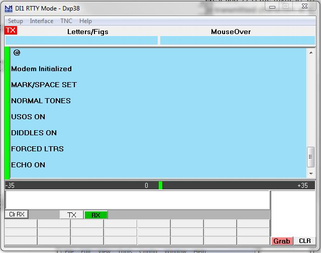
Configuring a DXP-38 in one of the additional RX windows
The DXP-38 can be configured to be used in one of the additional RX-only windows. To do so, use the Setup > Open Add. RX Window menu item in the Digital Interface window. If this is the first time this window has been opened, the Setup window will open, otherwise you may have to use the Setup menu item in the RX window:
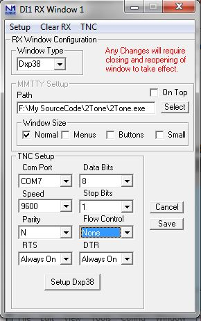
Select Dxp38 as the window type. The MMTTY Setup section is not used for the DXP-38. Under TNC Setup, select the COM port used for the DXP-38 and set the other parameters to 9600, N, 8, 1, no flow control, DTR and RTS both Always On. Once you click the Save button to save the configuration, close and reopen the RX window. The following screen shot is from an older version of the Logger, so yours may not look exactly like this, but you should see the same initialization messages on startup:
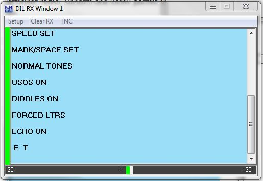
HAL ST-8000 Setup (not supported)
The HAL ST-8000 TNC is not supported and will not work with N1MM Logger as the baud rate used by the HAL is 45 baud and the serial port control in N1MM will only go as low as 110 baud…
KAM Setup
- Launch Hyperterm and set its parameters to 9600 bps, 8 databits, no-parity, 1 stopbit and no flow control
- Connect the KAM to the port configured in Hyperterm
- Turn on the KAM
- When you see the message ‘Press (*) to set Baud Rate, press the “*” button’
- Then set your callsign as prompted
- To place the unit into RTTY mode type “RTTY”
- Also make sure the unit is set up for software handshaking XFLOW = ON
- Once you are communicating with the KAM and have it in the RTTY mode, you can also tune in a RTTY signal and it will decode and print on the Hyperterm window
- Now try to transmit by typing a Ctrl+C and a “T” on the keyboard followed by several characters that you wish to transmit. To get back to receive, type a Ctrl+C and a “R”
- If you have problems, consult your KAM manual
- Now exit the Hyperterm program and start Logger
Below are sample RTTY settings for the KAM TNC
| AUTOCR | 0 | AUTOLF | ON | AUTOSTRT | OFF |
| BKONDEL | ON | CD | SOFTWARE | CRADD | OFF |
| DIDDLE | ON | ECHO | ON | FILTER | OFF |
| FSKINV | OFF | INVERT | OFF | LFSUP | OFF |
| LOWTONES | OFF | MARK | 2125HZ | RBAUD | 45 |
| SHIFT | 170 | SPACE | 2295HZ | USOS | ON |
| XFLOW | ON | XMITECHO | ON | – | – |
There are three parts in setting up N1MM logger to work with the KAM.
1. Port configuration in the Configurer under the Hardware tab:
- The serial port used by the KAM should have a checkmark in the Digital check box
2. Digital configuration (Configurer, Digital Modes tab)
- Set the TU Type to “Other” and configure the port for 9600 baud, N,8,1 and none
3. Macro Creation required to control the KAM (Digital Interface Setup window, Message Setup tab)
- Select the “Other” Digital Message Set
- Set the TX macro to: {Ctrl-C}T
- this programs the {TX} macro to put the KAM into transmit
- Set the RX macro to: {Ctrl-C}E
- programs the {RX} macro to return to receive after the message is completed
- Set the ESC macro to: {Ctrl-C}R
- Use the Esc key to immediately return the system to receive without sending unsent text that may still be in the transmit buffer
- You can now program your messages with the {TX} and {RX} macros, for example
- CQ message: {TX} CQ CQ CQ DE W3PP W3PP W3PP KKK {RX}
PK-232 Setup
- Make sure the PK-232 autobaud is set and the unit is set to RTTY mode
- Launch Hyperterm and set its parameters to 1200 baud, 8-data, no-parity, 2 stop bits, and no flow control
- Connect the PK-232 to the port configured in Hyperterm
- Turn on the PK-232
- Type a few “*” characters so your PK-232 will autobaud to the 1200 baud rate
- Now place the PK-232 in the RTTY mode by typing the command “BAUDOT”. It should respond OPMODE now BAUDOT
- Turn the threshold pot full clockwise and make sure the LED is on
- Also make sure the unit is set up for software handshaking XFLOW = ON
- Once you are communicating with the PK-232 and have it in the BAUDOT mode, you can also tune in a RTTY signal and it will decode and print on the Hyperterm window
- Now try a transmit by typing a “X” on the keyboard followed by several characters that you wish to transmit. To get back to receive, type a Ctrl+C and a “R”
- If you have problems, consult your PK-232 manual
- Now exit the Hyperterm program and start Logger. In the DI Setup window under the Macro Setup tab, select the “Other” Digital Macro Set, and program the TX, RX and Esc buttons as follows:
- TX: X{ENTER}
- RX: {CTRL-D}
- Esc: {CTRL-C}R{ENTER}TC{ENTER}
- If this has been done correctly, the {TX} and {RX} macros in your messages should now work correctly, and the Esc key should be able to interrupt (abort) an outgoing message immediately when it is pressed
Setting up the PK-232
By John VK4WPX / VK4CEJ
Setting up the PK-232 for RTTY is very simple and straightforward.
- First, open the ‘Configurer’ (On the main logging window click Config, Configure Ports, Telnet addresses, Other)
- Click the Hardware tab
- Click in the box adjacent to the COM port that you have your PK-232 connected to in the column labeled ‘Digital’
- See picture below, the example here shows the PK-232 on COM-2
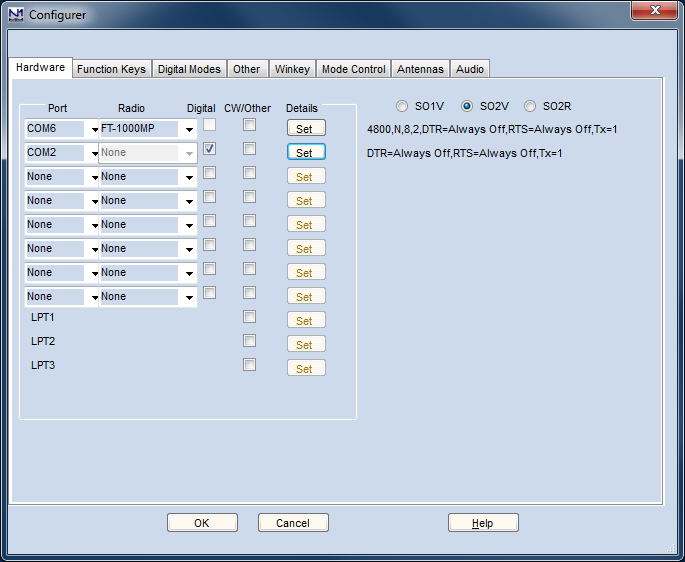
- Next, click on the Digital Modes tab and set up the Digital Interface 1 parameters
- The example in the picture below shows that the PK-232 is set for 9600 baud, no parity and 8 data bits
Setting up macros and the main logging window “F” keys for the PK-232 is also really very simple.
- Modify any existing macros that came pre-configured by replacing every instance of ‘ {TX} ‘ with ‘ {Ctrl-C}Xmit{ENTER} ‘
- I found that the command did not work every time unless it was followed by the {ENTER}
- or, if the macro does not have {TX} or {RX} in it and you want it to start transmitting or go to receive, add those commands and, replace every instance of {RX} with {Ctrl-D}
- Example: F1 “CQ” macro would therefore be ” {Ctrl-C}Xmit{ENTER}CQ CQ CQ DE * * * K{Ctrl-D} “
- Example: F5 macro “Hiscall” would be ” {Ctrl-C}Xmit{ENTER}! ”
- Which would leave the rig in transmit mode so that you could type more info in the transmit window
- To return to receive, press Ctrl+D (hold down the Ctrl key and press D)
SCS PTC Setup
- Take the PTC as you use it for other digimode programs e.g. ALPHA (by DH7RG), XPWIN (By KF7XP), LOGGER (by K4CY)
- Set the PTC to SERBAUD 19200 (not AUTO ! ) > switch the PTC OFF
- Start N1MMLogger and go to ‘Config | Configure Ports, Telnet Address, Other’, Select the tab ‘Digital Modes’. Set ‘Digital Interface 1 TU Type’ to ‘CW/Other’, set the used serial port to 19200 Baud, N-8-1-none. Set the ‘Digital Interface 2 TU Type’ to ‘None’. Save with ‘OK’
- Click on Windows and select Digital Interface
- Be sure that the PTC is connected to the right serial port and switch it ON and the start info will appear in the upper window finished by the prompt cmd: If you can’t see anything check serial port and settings
- Click in the lower window, enter with the keyboard ‘Escape+Shift bau 45 ENTER’ the PTC will switch to RTTY (look at the PTC mode display). Add ‘Escape+Shift term 1 ENTER’ to switch the PTC to echo the transmitted signs in the upper window. Note : Escape without Shift will switch the cursor to the main window
- In the open Digital Interface select ‘File | Settings’ and select Tab: ‘Macro Setup’. Select behind ‘Digital Macro Set’ ‘Other 1’. Now three buttons appear with TX, RX and ESC on it. These buttons have to filled with the sequence to put the PTC in TX and RX and to get a correct function for canceling the AUTO-CQ function or make a break with the ESC-key on the keyboard
- Digital Macro Set: Other 1
- TX button: {Ctrl-Y} NB. in capital letters
- Now the macro {TX} can be used to switch the TX ON
- RX button: {Ctrl-Y} NB. in capital letters
- Now the macro {RX} can be used to switch the TX OFF
- ESC button: {ESC}CLR{ENTER}{Ctrl-D}{ENTER}
- The macro will reset the PTC-2 to PACTOR, clear the TX buffer and switch the PTC-2 back to RTTY
- There are a maximum of 24 extra functionkeys. One of them may be configured to switch the PTC-2 from the default state PACTOR to RTTY
- Name button: RTTY
- Contents button: {ESC}clear{ENTER}{ESC}bau 45{ENTER}{ESC}term 1{ENTER}
- Every time you start the PTC-2 you may click on this key to start the RTTY-mode. You need ‘term 1’ to get a delayed echo on the RX-window when your text is transmitted
- You may generate more macros with simple QSO texts using the installed N1MMLogger macros as !, *, DATE, TIME etc
- Don’t forget to start a functionkey with {TX} and at the end place {RX} to switch back to receive
- See for some macro examples at macros page
TinyFSK by Andy Flowers, K0SM
TinyFSK is a software program written for the Arduino hardware platform that produces FSK RTTY by emulating a traditional TNC for transmitting. TinyFSK does not have a receive capability, so you use one of the sound card interface choices for receive. The following configuration can be used with the popular Mortty RTTY interface running the TinyFSK sketch.
These instructions assume that you have connected your Arduino to your computer, uploaded the TinyFSK “sketch” to the Arduino, installed the hardware keying interface for PTT and FSK from the Arduino to your radio, and that you know the COM port number that Windows has assigned to the Arduino. For information on how to perform these preliminary tasks, visit K0SM’s website HERE or google “TinyFSK.” There are many helpful TinyFSK tutorials on the Internet.
The instructions in the next two sections should work with any of the sound card digital engines, including 2Tone. However, if you are using 2Tone as your primary digital engine for receiving in the main Digital Interface window, there is an alternative method available as well. Unlike the other digital engine programs, 2Tone can support TinyFSK directly. To use this feature, you would configure the N1MM+ Configurer and Digital Setup windows the same as if you were using AFSK, except that in 2Tone’s own setup window you tell 2Tone to use TinyFSK, and in the N1MM+ Configurer under the Mode Control tab, Mode sent to radio, you tell the program you want to put the radio into RTTY (FSK) mode, not AFSK or SSB mode. Do not configure the FSK serial port in the Configurer under the Hardware tab, and do not select TinyFSK as the TU type under the Digital Modes tab. Let 2Tone take care of all of that. Of course, if you then decide to switch from 2Tone to MMTTY as your primary digital engine, you will have to change the setup in the Configurer as described in the next two sections.
TinyFSK In the N1MM Configurer
From the N1MM Logger Entry Window, select >Config >Configure Ports, Mode Control…
- In the Configurer Dialog Window, select the >Hardware tab
- In the Port column, identify the serial port connected to the Arduino
- In the Digi column, check the box adjacent to the Arduino port number
- In the Details column, press the adjacent Set button and set DTR = Always On and RTS = Always OFF
- Set the Radio Nr to the radio number (1 in SO1R and SO2V, either 1 or 2 in SO2R depending on which radio the TinyFSK will be keying)
- Set the Dig Wnd Nr to correspond with the Digital Interface window the TinyFSK will be associated with and transmitting from
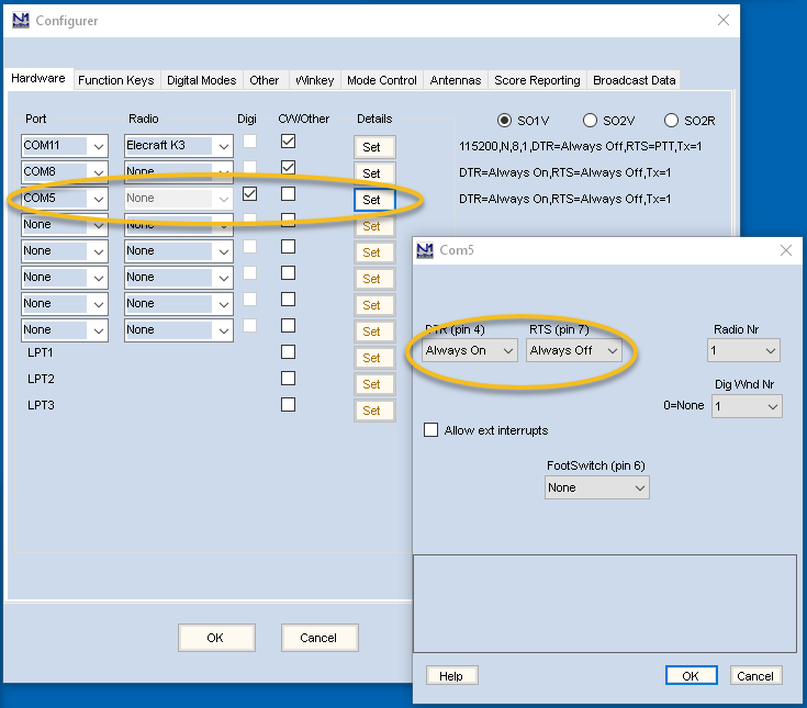
- In the Configurer Dialog Window, select the >Digital Modes tab
- Under Digital Interface 1, TU Type
- Select TinyFSK, and enter the serial port settings as 9600, N, 8, 1, None
- If planning to operate SO2V, under Digital Interface 2, TU Type
- Select TinyFSK, and enter the serial port settings as 9600, N, 8, 1, None
- Under Digital Interface 1, TU Type
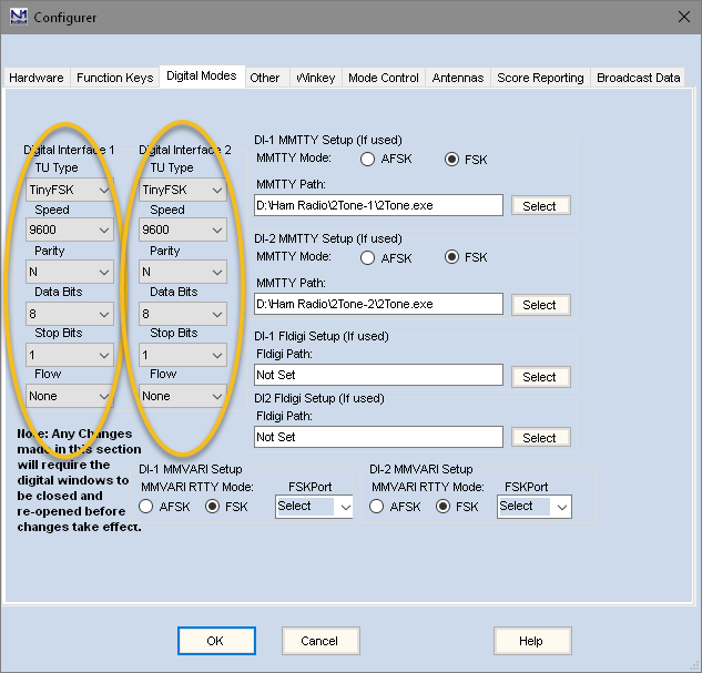
- Note that when you use TinyFSK, you are in effect using a TNC to transmit, but a sound card program such as MMTTY to receive. Therefore, in addition to configuring the TinyFSK serial port on the left side of this window, you also need to configure the sound card interface you will be using to receive with on the right side of the window. Since you are only using the sound card interface to receive, you should configure it for AFSK (even though you are actually transmitting using FSK), in order to prevent the sound card interface from trying to key FSK in parallel with the TinyFSK. You can configure the sound card program to use a sound card output that is otherwise unused. Do not configure the sound card program (e.g. MMTTY) to transmit using FSK, as that could conflict with N1MM+’s use of the TinyFSK for FSK keying.
- In the Configurer Dialog Window, select the >Mode Control tab
- On the right side, under Mode sent to Radio, in the row for RTTY set the “Mode sent to radio” to RTTY (to put the radio into FSK mode when the program is in RTTY mode)
TinyFSK In the Digital Interface (DI)
From the N1MM Logger Digital Interface (DI) Window, select >Setup >Settings
- In the Digital Setup Window
- Under the General/MMTTY Setup tab, at the right side, set the Preferred RTTY Interface to whichever sound card program you are using to receive with (if you are using 2Tone, select the MMTTY setting)
- Under the Message Setup tab, Digital Message Set, select Other, TinyFSK
- Press, in sequence, the three buttons labeled TX, RX, ESC. For each of these verify the following settings
- Press TX: Message Text = [{ENTER} , Message Caption = TX
- Press RX: Message Text = ]{ENTER} , Message Caption = RX
- Press ESC: Message Text = \ , Message Caption = ESC
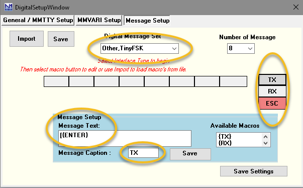
K1EL Winkeyer 3.1 RTTY Interface
Starting with version 3.1, the K1EL Winkeyer can do FSK RTTY keying in addition to CW keying. The Winkeyer does not have a receive capability, so you use one of the sound card interface choices to receive with.
These instructions assume you have connected an FSK keying cable between the Winkeyer and your radio’s FSK keying input, as described in the Winkeyer 3.1 documentation. Note also that this method is not available with older versions of Winkeyer.
Winkeyer RTTY in the Configurer
From the N1MM Logger Entry Window, select >Config >Configure Ports, Mode Control…
If you are already using the Winkeyer for CW, skip this paragraph. If not, you must configure a serial port for it the same as if you were using it for CW (see the instructions for doing this on the Configurer page).
In the Configurer Dialog Window, select the >Digital Modes tab
- Under Digital Interface 1, TU Type
- Select Winkey
- If planning to operate SO2V, under Digital Interface 2, TU Type
- Select Winkey
- Note that when you use the Winkeyer for RTTY, you are in effect using a TNC to transmit, but a sound card program such as MMTTY to receive. Therefore, in addition to configuring the Winkeyer for RTTY, you also need to configure the sound card interface you will be using to receive with on the right side of the window. Since you are only using the sound card interface to receive, you should configure it for AFSK (even though you are actually transmitting using FSK), in order to prevent the sound card interface from trying to key FSK in parallel with the WInkeyer. You can configure the sound card program to use a sound card output that is otherwise unused. Do not configure the sound card program (e.g. MMTTY) to transmit using FSK, as that could conflict with N1MM+’s use of the Winkeyer for FSK keying.
In the Configurer Dialog Window, select the >Winkey tab and check the check box called “Enable RTTY Mode using Winkey”.
In the Configurer Dialog Window, select the >Mode Control tab
- On the right side, under Mode sent to Radio, in the row for RTTY set the “Mode sent to radio” to RTTY (to put the radio into FSK mode when the program is in RTTY mode)
Winkeyer RTTY in the Digital Interface
From the N1MM Logger Digital Interface (DI) Window, select >Setup >Settings
In the Digital Setup Window
- Under the General/MMTTY Setup tab, at the right side, set the Preferred RTTY Interface to whichever sound card program you are using to receive with (if you are using 2Tone, select the MMTTY setting)
- Under the Message Setup tab, Digital Message Set, select Other, TinyFSK, Winkey
- Press, in sequence, the three buttons labeled TX, RX, ESC. For each of these verify the following settings
- Press TX: Message Text = [ , Message Caption = TX
- Press RX: Message Text = ] , Message Caption = RX
- Press ESC: Message Text = \ , Message Caption = ESC