The Bandmap Window
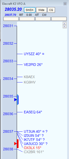
Your Bandmap window will be similar to this one.
Key Features
The Bandmap window represents a VFO or a radio. There are three scenarios: one radio with 1 VFO displayed (SO1V); one radio with 2 VFOs displayed (SO2V); or two radios with one VFO shown for each radio (SO2R). Bandmaps can be zoomed down to just a few KHz or up to the entire band.
With one radio in SO1V mode, only one bandmap can be displayed. With one radio in SO2V mode, two bandmaps may be displayed, one for each Entry window. Each bandmap represents one VFO. With two radios the operation is exactly the same, except that each bandmap represents one of the radios.
To switch the Entry or RX Focus from one bandmap to the other, Press “\”. To switch both the Transmit and Entry/RX Focuses, press “Pause”.
Frequencies in the Bandmap window may be displayed either increasing from top to bottom (with the lowest frequency at the top as in the screenshot above), or from bottom to top (with the lowest frequency at the bottom). There is an entry in the right-click menu to choose the direction. However, there is an interaction with the Spectrum Display window that affects this. If the Spectrum Display window is open in the horizontal (“Column”) orientation, frequencies in the Bandmap window will be displayed with the lowest frequency at the bottom regardless of the setting of this option in the Bandmap window. In order to view the Bandmap window with the lowest frequency at the top, the Spectrum Display window must either be closed or in the vertical (“Bar”) orientation, and the direction option in the right-click menu must be unchecked.
The reason for this is that the direction is forced by the program to be consistent between the Bandmap window and the Spectrum Display window. The direction in the Spectrum Display window can be changed when that window is in the vertical orientation, but not when it is oriented horizontally, and therefore only one direction is available in the Bandmap window when the Spectrum Display window is oriented horizontally.
The Bandmap window includes the following basic features:
- Current receiving frequency is denoted by a blue arrow. If split, the current transmit frequency is denoted by a red arrow. At the point of each arrow is a graphic depiction of whether the radio is currently in a wide or narrow filter setting for its current mode.
In this example, the radio is in the CW band. The dark blue and red bands are a notional (not actual) representation of the CW filter bandwidth, while the light blue represents the tuning tolerance set in the Configurer. If you tune the VFO outside that range, any call-sign captured into the Entry window’s call-frame or brought into the Entry window’s call-sign textbox will be erased. If you have elected to set the Config menu option “QSYing wipes the call and spots QSO in bandmap,” the station you did not work is spotted in boldface as a reminder to come back to it.
- The up/down arrows in the upper right control the size of text in the window, independent of the global setting for the rest of the program.
- Beside the up/down arrows is a lock icon. If the window is locked, the frequency display in the window will not be changed by the program as a result of clicking on a spot or changing the radio frequency.
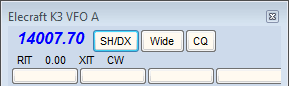
- In the title bar, the first line of smaller type shows the name of the connected radio, and the VFO or radio denoted by the Bandmap. Immediately below in larger type is the receiving frequency and below that, in smaller type, is the transmit frequency if different (when Split). To the right are three clickable buttons. The first sends SH/DX to the Telnet cluster to which you’re connected. The second toggles between wide and narrow filter settings, always displaying the one that is currently selected. Clicking on the third (labeled “CQ”) will jump your radio’s VFO to the last frequency on which you called CQ on the current band. The text “CQ-Frequency” is shown on the Bandmap on the frequency where you last went into Run mode, and used as the target for this function.
- Below the three buttons are text prompts to remind you that RIT or XIT are on (by turning red), report the amount of the RIT or XIT offset, and remind you what mode the radio is in. Each of these is clickable to turn the function off or on, or to step through the available modes – see Clickable Text Messages below.
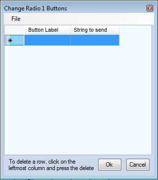
- In the bottom line of the header are four (or more, up to 36) programmable message or radio control buttons. Right-click on any of them, and an editing dialog will appear, in which you can edit the contents of existing buttons, or add new buttons simply by adding new lines to the list:
- The buttons appear in groups (rows), four buttons per row. In SO2R or SO2V, there is a separate set of buttons for each bandmap window (Radio 1 and Radio2, or VFO A and VFO B).
- Once they have been programmed, the buttons in the bandmap window (or in SO2R/SO2V, the bandmap window for the radio or VFO that has keyboard focus) can be accessed from the keyboard using Ctrl+Alt+Shift+0 through Ctrl+Alt+Shift+Z key combinations (or by using AutoHotKey or an external programmable keypad programmed to send those key combinations). The button in the upper left corner is button 0. Button 9 is the third row, second column. The tenth button is the third row, third column (button “A”). The next button (third row, fourth column) is button “B”. Etc.
- The string to send is in the format of a function key message or a radio control macro (e.g. CAT1ASC or CAT1HEX macro). Enter a label into the button label column and a CW/SSB/Digi message or a radio control macro in the same format you would use in a function key message, including the curly braces. into the “String to send” column. Now clicking on this button will send the selected command to the radio. You can use “|” to set up commands and labels to toggle between the information on either side of the button. For an Icom 7300, here are some radio control examples:
- Scope on|Scope off {CAT1HEX FEFE94E0271001FD}|{CAT1HEX FEFE94E0271000FD}
- 100w|50w|20w {CAT1HEX FEFE94E0140A0255FD}|{CAT1HEX FEFE94E0140A0128FD}|{CAT1HEX FEFE94E0140A0051FD}
- IP+ on|IP+ off {CAT1HEX FEFE94E01a0701FD}|{CAT1HEX FEFE94E01A0700FD}
- NR On|NR Off {CAT1HEX FEFE94E0164001FD}|{CAT1HEX FEFE94E0164000FD}
- NB On |NB Off {CAT1HEX FEFE94E0162201FD}|{CAT1HEX FEFE94E0162200FD}
- AF 20|AF 40|AF 60 {CAT1HEX FEFE94E014010051FD}|{CAT1HEX FEFE94E014010102FD}|{CAT1HEX FEFE94E014010153FD}
- Mon On|Mon Off {CAT1HEX FEFE94E0164501FD}|{CAT1HEX FEFE94E0164500FD}
- Fast|Mid|Slow {CAT1HEX FEFE94E0161201FD}|{CAT1HEX FEFE94E0161202FD}|{CAT1HEX FEFE94E0161203FD}
- Vox On|Vox Off {CAT1HEX FEFE94E0164601FD}|{CAT1HEX FEFE94E0164600FD}
- No Sp|Split {CAT1HEX FEFE94E00F00FD}|{CAT1HEX FEFE94E00F01FD}
- VFOA {CAT1HEX FEFE94E00700FD}
- VFOB {CAT1HEX FEFE94E00701FD}
- A=B {CAT1HEX FEFE94E007A0FD}
- A/B {CAT1HEX FEFE94E007B0FD}
- CW {CAT1HEX FEFE94E0010302FD}
- LSB {CAT1HEX FEFE94E0010002FD}
- USB {CAT1HEX FEFE94E0010102FD}
- 0 dB|20 dB {CAT1HEX FEFE94E01100FD}|{CAT1HEX FEFE94E01120FD}
- Vox|PTT {CAT1HEX FEFE94E0164601FD}|{CAT1HEX FEFE94E0164600FD}
- ClearIt {ClearRIT}{CAT1HEX FEFE94E0210100FD}
- Run {RUN}
- S&&P {S&P}
- No Pre|Pre 1|Pre 2 {CAT1HEX FEFE94E0160200FD}|{CAT1HEX FEFE94E0160201FD}|{CAT1HEX FEFE94E0160202FD}
- You can mouse over any call-sign on the Bandmap and a tool-tip will appear briefly, telling you when the station was spotted, by whom, and anything else about the spot. In addition, when a spot is less than three minutes old NEW will be placed behind the call and bearing on the Bandmap. When the spot includes split frequency information, the station’s receiving (QSX) frequency will be shown behind the bearing. Splits are shown as 3 digits on HF. The bearing to a station is shown only for stations outside your own country, with exceptions for USA and Canada.
- Spots of stations close to their sunrise/sunset time are marked with a sunrise/sunset indicator “¤”.
- CW Skimmer spots are marked with “#” in spotter’s call-sign as skimmer spot in the bandmaps (see picture at right above). If you are the spotter, then the spots are marked with a “!”.
Colors of the Incoming Spots
- Blue: Will be a good QSO, not a multiplier
- Red: Single Multiplier Example: CQWW – QSO is either zone or country multiplier (one multiplier)
- Green: Double or better Multiplier Example: CQWW – QSO is a zone and a country multiplier (two multipliers)
- Gray: Dupe
- Bold – This is a self-spotted call. In this context “self spotted” means that the user typed in the call, not that the spot came from the spotting network.
Note– A different set of color codes is provided for the WAE contests, to assist with QTCs. Read about it here.
Display and Adjustment of Band Plans in Background of Bandmap Frequency Scale
The band plans (mode-based sub band limits) in the Bandmap window are important for other parts of the program besides the Bandmap window itself. These limits determine what mode the program assigns to incoming spots in the Telnet window if those spots do not contain the mode in the spot notes. This in turn can affect how the spots are filtered and whether or not they are passed from the Telnet window to the Bandmap and Available Mults & Qs window. Also, if the “Follow band plan” option has been chosen in the Configurer under the Mode Control tab, the mode that contacts are logged in will depend on the frequency. For these reasons it is important to understand how to set the sub band limits appropriately for the type of contest you are entering. The appropriate sub band limits can vary depending on the contest (DX vs. domestic, SSB vx. CW vs. digital vs. mixed mode). Inappropriate choice of the sub band limits is a frequent cause of logging errors.
The illustration above depicts the new feature in N1MM Logger+ for displaying and modifying band plans. This is an alternative to the procedure provided on the Config menu of the Entry window. Note: This is not real – there is no digital sub-band inside the SSB portion of the band. It only illustrates all of the options.
There are some considerations to be aware of before you begin.
- You can only designate CW and digital band plan segments. It is assumed that anything not designated for one of those modes is SSB territory.
- You can only designate one band segment per mode, but by understanding the rules of precedence used by the program you should be able to handle this. For example, SSB is defined as not CW and not digital, so there is no need to set SSB limits.
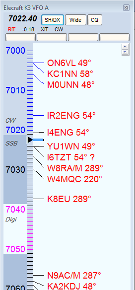
To set the band plans from the Bandmap window, right-click on a frequency number in the Bandmap. That will bring up the following menu:
Instead of using this method, you may prefer to use “Change Band Plan” in the Entry Window, Config menu.
Note that you click on the frequency you want to set, and then click in the sub-menu to set it. For example, if you want to set the digital sub-band minimum frequency on 40 meters for a major RTTY contest, you might click on “7020” and then click “Set as Digi sub band min freq”.
- The “Set” options are self-explanatory. Options that are not available on a given band or frequency are greyed out.
- The “Remove” option is for CW contests, when many CW operators migrate into what are normally digital sub-bands. To prevent these being logged as RTTY, you can remove the digital sub-bands and re-establish them after the contest.
Keyboard Shortcuts
- Numeric keypad + key – Zoom In on the Bandmap associated with the Entry window that has entry focus.
- Numeric keypad – key – Zoom out on the Bandmap associated with the Entry window that has entry focus.
- Shift – Numeric keypad + key – In SO2V or SO2R, zoom in on the Bandmap associated with the Entry window that does not have entry focus.
- Shift – Numeric keypad – key – Zoom out on the Bandmap associated with the Entry window that does not have entry focus.
Jumping to Spots on the active radio or VFO (the one with the Entry focus)
- Ctrl+Down Arrow – Jump to next spot higher in frequency.
- Ctrl+Up Arrow – Jump to next spot lower in frequency.
- Ctrl+Alt+Down Arrow – Jump to next spot higher in frequency that is a multiplier.
- Ctrl+Alt+Up Arrow – Jump to next spot lower in frequency that is a multiplier.
Jumping to Spots on non active radio/VFO
- Ctrl+Shift+Down Arrow – Jump to next spot higher in frequency on the inactive radio/VFO. This will skip over CQ-Frequency when radios or VFOs are on the same band. Proper keystroke operation is radio dependent. Disabled for SO1V.
- Ctrl+Shift+Up Arrow – Jump to next spot lower in frequency on the inactive radio/VFO. This will skip over CQ-Frequency when radios/VFOs are on the same band. Proper keystroke operation is radio dependent. Disabled for SO1V.
- Shift+Ctrl+Alt+Down Arrow – Jump to next spot higher in frequency on the inactive radio/VFO that is a multiplier. If you are operating single mode, your mode won’t change when jumping between spots. Disabled for SO1V.
- Shift+Ctrl+Alt+Up Arrow – Jump to next spot lower in frequency on the inactive radio/VFO that is a multiplier. If you are operating single mode, your mode won’t change when jumping between spots. Disabled for SO1V.
- Shift+Alt+Q – Jumps to your last CQ frequency on the inactive VFO/radio. Disabled for SO1V.
Clickable Text Messages
These are found below the radio frequency at the top of the Bandmap.
- RIT Offset (already 0.00 in the illustration) – Click this label to clear the RIT offset.
- RIT – Click this label to toggle the RIT on and off.
- XIT – Click this label to toggle the XIT on and off.
- CW/USB/LSB/RTTY/PSK/AFSK/AM/FM – Click this label to toggle from USB/LSB (band-specific) through RTTY to CW/PSK/AFSK/AM/FM (radio dependent).
Mouse Actions
- Click on frequency – Moves the active VFO/radio to that frequency.
- Shift+Click on frequency (SO2R only) in inactive Bandmap – Tune the non-active radio without changing window focus. Allows you to be active and sending on one radio and change the frequency on the non-active radio without changing Entry window focus.
- Shift+Click on bandmap callsign (SO2R only) in inactive Bandmap – Same as Shift+Click on Frequency with the addition that the callsign is placed in the non-active radio’s Entry window call-frame.
- Click on call – Jump to that frequency and place the call in the Entry window call-frame. When the call-sign field is empty, hit Space to copy the call-sign from the Entry window call-frame to the call-sign textbox.
- Double-Click on call – Jump to that frequency, place call in the Entry window call-frame and the call-sign textbox, replacing anything that was previously there.
- Click on or to the left of the vertical frequency scale – Jump to that frequency.
- Click frequency label – Jump to that frequency.
- Right Click call – Display the right-click menu for the selected call (see Right-Click menu below).
- The selected call will be shown in italic font and underlined when the right-click menu is open
- Right Click anywhere else – Display the right-click menu with some options grayed out which are call related.
- Scroll wheel with the mouse cursor in the frequency part of the main window – Pan the display, i.e. move the range of frequencies displayed up or down the band.
- Scroll wheel with the mouse cursor in the call sign part of the main window – Zoom the display, i.e. change the range of frequencies displayed.
Right-click Menu Options
If you right click in the Bandmap window the right-click menu will appear. If you do not click on a particular spot, certain options will be grayed out.
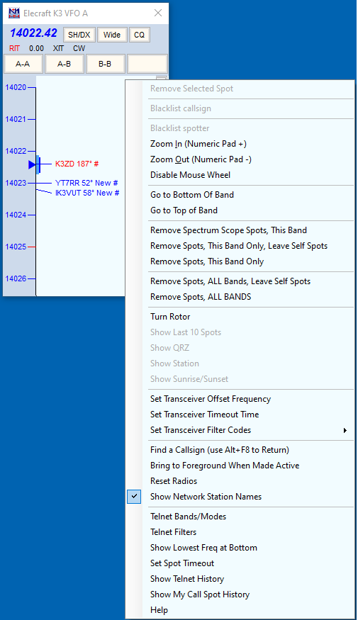
- Remove Selected Spot – equivalent to Alt+D with the spot callsign in the call-frame; removes the selected spot. Grayed-out when not right-clicking on a particular spot.
If your mouse has a clickable scroll wheel, you can also delete spots from the Bandmap simply by clicking on them with it.
- Blacklist callsign – if you click on this option with a callsign selected and the Filter Blacklisted Spot Calls option in the Filters tab of the Telnet window’s right-click menu is enabled, subsequent spots of that callsign will not be displayed on the Bandmap or in the Available window. Used to get rid of busted spots that recur often, such as LW3LPL. To edit the list of blacklisted spots, or to remove a call from the list, use the Edit option on the filter tab.
- Blacklist spotter – designed in particular for use when an RBN station is feeding spots that are badly off-frequency (due to I/Q image problems) or otherwise defective. Could also be used for the occasional harasser on traditional DX clusters. Again, this feature is enabled/disabled in the Filters tab of the Telnet window’s right-click menu; the blacklist can also be edited from that tab.
- Zoom In (Numeric Pad + or use the mouse wheel with the mouse over the calls portion of the Bandmap window) – Show a smaller frequency range on the Bandmap that has entry/RX focus; spreads frequency markers and spotted call signs farther apart.
- Zoom Out (Numeric Pad – or use the mouse wheel with the mouse over the calls portion of the Bandmap window) – Show a larger frequency range on the Bandmap that has entry/RX focus; brings frequency markers and spotted call signs closer together.
- Disable Mouse Wheel – Does what it says. When the mouse wheel is not disabled, it either pans the frequency display up or down the band when used in the frequency scale part of the window, or it zooms the display in or out when used in the call sign part of the window. Disabling the mouse wheel with this menu item prevents these actions. Note that changing the range of frequencies displayed as a result of clicking on a spot or changing the radio’s frequency is controlled by the lock icon in the top right corner of the call sign portion of the window and not by this right-click option.
- Go to Bottom Of Band – Go to the bottom of this SSB/CW subband.
- Go to Top of Band – Go to the top of this SSB/CW subband.
- Remove Spectrum Scope Spots, This Band – Remove self-spots that originated from signals above the threshold in the Spectrum Display window
- Remove Spots, This Band Only, Leave Self Spots – Does what it says.
- Remove Spots, This Band Only – Does what it says.
- Remove Spots, ALL Bands, Leave Self Spots – Does what it says.
- Remove Spots, ALL BANDS – Does what it says.
- Turn Rotor – Turn the rotor to point to the heading of the callsign in the spots
- Show Last 10 Spots – click this option (which is gray unless a callsign has been clicked on) and the cluster will be asked for the last 10 spots of that station. These are displayed in the Telnet window.
- Show QRZ – requests address information from the DX cluster for the selected callsign
- Show Station – sends the SH/STA [callsign] command to the DX cluster
- Show QSL/Packet – sends the SH/QSL [callsign] command to the DX cluster
- Show Sunrise/Sunset – sends the SH/SUN [callsign] command to the DX cluster
- Set Transceiver Offset Frequency – This is for transverter support. The offset is saved when the program closes and read again when opened. Remember to enter the frequency of the transceiver and not that of the transverter when going into split mode (Alt+F7). Information how to fill in this table (which frequencies to enter and how to calculate the IF frequency) can be found in the VHF and Up Contesting chapter.

- Set Transceiver Timeout Time – Sets the time interval after which, if no communication with a radio is occurring, the program will alert you. The value is set for each radio (default is 15 seconds). Entering a value of zero will disable the timeout function. Entering a negative number will set the time out value to 15 seconds. Entering a number that is too large for the program variable will set the timeout to the program maximum. The positive minimum is 5 seconds.
- Set Transceiver Filter Codes – This setting controls what is sent to your radio when you click the “Wide/Narrow” button at the top of the Bandmap to toggle between wide and narrow filters. If no value is set, then the program uses the default values set for your radio.
You will be prompted for the wide or narrow string to set the filters. For Kenwood, it’s pretty easy. You just look up in your manual the string you want and enter it. For other radios, like FT-1000MP, it’s harder. You must enter a series of space-delimited codes in DECIMAL. Therefore, when an FT-1000MP filter code of 0 0 0 0 8C is required, you must enter 0 0 0 0 140 (8C hex).
To reset to the default values in the program enter a space and press the OK button. It is possible to use {CR} in the filter codes which will be replaced with the return character. These selection are disabled when manual radio is selected (i.e. no radio selected).
- CW Wide
- CW Narrow
- SSB Wide
- SSB Narrow
- Digi Wide
- Digi Narrow
- Find a Callsign (use Alt-F8 to Return) – This option allows you to search for a particular callsign in the bandmap. Searches from current frequency up to find each instance.
- Bring to Foreground When Made Active – This brings the active bandmap to the foreground. If you don’t have enough monitor space, you can place Bandmaps on top of one another, and when you move the entry focus between Entry windows, the active bandmap will be shown hiding the non-active bandmap.
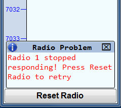
- Reset Radios – Allow manual reset of all attached radios. When contact with a radio is lost the dialog below will appear at the bottom of the Bandmap window. The “Radio Problem” popup will disappear after a few seconds, but the “Reset Radio” button will remain until communications with the radio has been restarted. Once any physical problem (such as a disconnected cable) has been corrected, you can click on the “Reset Radio” button or right-click on the bandmap and choose “Reset Radios” from the right-click menu to restart the connection.
- Show Network Station Names – When in networked computer mode, show the frequency that another networked station is on (if within the range of the bandmap display)
- Telnet Bands/Modes – opens the Bands/Modes tab of the Telnet window so you can adjust which bands and modes will be displayed on Bandmaps and in the Available Mults & Qs window.
- Telnet Filters – opens the Filters tab of the Telnet window so you can adjust which spots will be displayed on Bandmaps and in the Available Mults & Qs window.
- Show Lowest Freq at Bottom – This option may be used to change the direction of frequencies in the Bandmap window (lowest frequency at the top versus lowest frequency at the bottom), provided that the Spectrum Display window is not open in the horizontal (“Column”) orientation. If the Spectrum Display window is opened in the horizontal orientation, this option will be greyed out and frequencies in the Bandmap window will be displayed with the lowest frequency at the bottom regardless of the previous setting of this option. In order to view the Bandmap window with the lowest frequency at the top, the Spectrum Display window must either be closed or in the vertical (“Bar”) orientation, and this option in the Bandmap window right-click menu must be unchecked.
- Set Spot Timeout – Set the length of time spots will remain on the bandmap before timing out and disappearing (unless re-spotted)
- Show Telnet History – Shows the Telnet history of any station on the bandmap. Select the station by right-clicking on it and then clicking on this option.
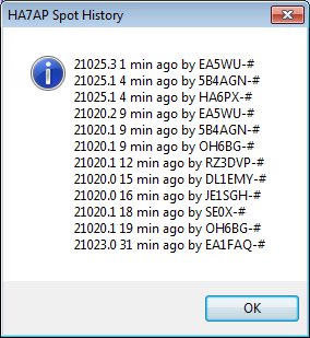
- Show My Call Spot History – Shows the recent Telnet history for spots of your station.
- Help – Show the help file for this window.
When the cluster to which you are connected is a DXSpider cluster, select ‘Format for DX Spider cluster’ on the Other tab in the Configurer.
Hovering with the mouse over a spot
Hovering with the mouse over a spot in the Bandmap gives the following info about the spotted station:
- Exact frequency sent by spotter.
- Call-sign of spotter.
- The time in minutes since the station was placed on the DX cluster network.
- Comments sent with the spot.
- The notation “Self Spotted” indicates that you spotted the station.
Hovering with the mouse over the blue arrow marking your receiving frequency – shows the exact frequency and tuning tolerance.
Example Bandmap Usage
by Tom, N1MM
In Search & Pounce (S&P) the call-frame will show you each spotted station as you come within “tuning tolerance” (user settable) of that station. I’m terrible at remembering whether I worked a station and on what frequency. With worked stations in the bandmap, the program will tell you that they are not workable again. You can tune by them more quickly. The same feature is useful in contests with unworkable stations.
In a contest like CQ WPX, with (basically) no value multipliers, here is how I use the Bandmap. Whenever I can’t get a run going I start S&P on a band with a lot of unworked stations (use the available window). I use Ctrl+Up and Ctrl+Down arrow to go to the next station. If that station is at the beginning of a QSO, I move to the next one. If the QSO is near the end, I wait and work the station. Then I move on. If I reach the top of the band, I start coming back down the band, working the ones I missed on the way up. If there is no station at a frequency, that’s my new running frequency!
In contests with valuable multipliers, you should use Ctrl+Alt up/down to get the multipliers first, then go back and get the QSOs.
If the rate drops fairly low, sweep the band using your VFO. That is where the old calls in the bandmap come in useful. If you copy a call, but it seems like it is going to take a long time to work him, tune to the next guy. If you have “QSYing wipes the call & spots QSO in bandmap” turned on, the call will be spotted in bold, so you can Ctrl+Up/Ctrl+Down to him later.
Remember: if a call is in the callframe, space will load it into the call textbox.
If all this seems very unfamiliar, you haven’t read the Key Assignments help (and/or the Key Assignments Shortlist).
Reading that single item is your single best time investment in using this program.
Spots and the time shown
When you hover with the mouse over a spot in the bandmap, it will show the relative age of a spot in minutes. The time shown here depends on the spot format. There are two formats for spots. One is for current spots, one is for SH/DX spots. Some clusters allow to show old spots in the current spot format. The program handles the two types of spots differently.
- Current spots go into the bandmap with the computer’s local (converted to UTC) time. This is to remove variations in cluster times and order the spots into the time they were received.
- Old spots are logged with the originating cluster’s time with the provision that it cannot be later than the current local (UTC) time.
With AR-Cluster you can display old spots with SH/DX or SH/FDX. It is recommended to use SH/DX, as it will be recognized as an old spot. Other cluster software may have similar capabilities.
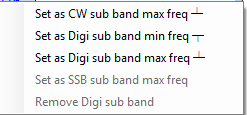
Red lines indicating US license frequencies
On the bandmap there are red lines to indicate extra, advanced and general portions of each band. Since US hams can operate only in their section and the sections of lower class licenses, it is in your interest to operate some in the higher portions of each band. Otherwise there are some US hams you will not ever be able to work.
The lines can be found on:
- SSB: 3775, 3850, 7225, 14175, 14225, 21225 and 21300.
- CW: 3525, 7025, 14025 and 21025.
- No lines on 160 and 10 meters.