Interfacing
Serial, Parallel and Sound Card Interfacing
Ports Used for Interfacing
The program can interface with your radio using several ports from the computer. These ports are:
- Serial port – A serial port can send CW, control PTT or communicate with your radio; with some radios you may be able to do all three on one port. Hardware serial ports are rapidly disappearing from most computers, but if the computer has open PCI bus slots. inexpensive serial and serial/parallel port cards are available. Alternatively, USB-to-serial adapters may be used.
- Parallel port – Parallel (LPT) port interfacing is quite flexible. In addition to controlling CW and PTT, N1MM Logger uses the LPT port to control popular SO2R control boxes, and to send band information to a band decoder for automatic antenna or bandpass filter switching. With one exception, USB-to-parallel adapters will not work here. Note also that you will still need a separate virtual or hardware serial port for radio control, because radio control cannot be done from a parallel port.
- USB port – Most computers now have multiple USB ports. USB-to-serial adapters can be used to provide full serial port capabilities, but be aware that not all such adapters (or their drivers) work well with N1MM Logger+. See USB Interface Devices for specifics. There are also many different interface devices available that use USB port control for a full gamut of capabilities. See the chapter Supported Hardware for more information.
- Sound card – N1MM Logger+ can use your computer’s sound card to record your contest QSOs, and also to send stored audio messages to your transmitter in response to function key presses. The sound card may be on the computer’s motherboard, or a separate card internal to the computer, or an external sound card interfaced to the computer with a USB cable. For these purposes, it is best to find a computer or sound card that has separate microphone and line input jacks, as well as a line out jack. Some sound cards (particularly in laptops) now come with only two jacks, or even with only one “combo” jack, and the input jack may not be switchable between microphone and line levels. If this is the case, you will not be able to run your microphone through your sound card and record QSOs at the same time.
Troubleshooting Com Port In Use Errors
Com Port In Use Error Messages – Occasionally Windows can get confused and orphan both physical and virtual comports. These ports are not visible to the user in Device Manager, but Windows will enumerate them causing failures when trying to create a virtual com port where one invisibly already exists. This procedure will in most cases allow the user to un-hide hidden com ports in order to delete them eliminating possible com port conflicts. Before starting, shut down your radio and close any programs what may be using the virtual com ports, like SmartSDR CAT or other third-part applications.
- Click Start, point to All Programs, point to Accessories, and then click Command Prompt.
- At a command prompt, type the following command , and then press ENTER: set devmgr_show_nonpresent_devices=1
- Type the following command a command prompt, and then press ENTER: start devmgmt.msc
- Troubleshoot the devices and drivers in Device Manager.
- Click Show hidden devices on the View menu in Device Manager before you can see all devices associated with the computer.
- Scroll down to the Ports section and you will be able to see all the hidden and unused COM ports. The hidden com ports have a grayed out icon next to them.
- To delete a particular port, click to highlight it and hit the Delete key on your keyboard. In the Confirm Device Removal dialog box, click OK.
- After you have deleted the unused and hidden COM ports, the list will show only those COM ports you use or may use in the future. Be careful not to delete com ports that are working properly.
- When you finish troubleshooting, close Device Manager.
- Type exit at the command prompt.
Note that when you close the command prompt window, Window clears the devmgr_show_nonpresent_devices=1 variable that you set in step 2 and prevents ghosted devices from being displayed when you click Show hidden devices.
Finally – if all else fails – this suggestion from Peter DF1LX: “I had this problem for some month. Nothing helped me what was mentionened in this thread. Only using the registry editor and searching for the comx value show, that another program, which never use any com port have a registry entry which show this com port. Deleting this registry entry and the problem was done. I would do this as last option if the given hints are not working.”
Radio interfacing
Radio manufacturers have supplied various means for interfacing radios with computers for radio control functions. All of these interfaces appear to the computer software like a standard RS-232 serial port, but the hardware actually used varies considerably. At a minimum, the features supported by radio control interfaces include reading and setting operating frequencies and modes. Most but not all radios that support radio control from a computer also supply commands for the computer to control TX/RX switching (PTT). Newer radios support control of a wide variety of other features, such as RIT/XIT control, switching of filters, and other functions.
The earliest radio control interfaces generally used TTL voltage levels on the radio connector which were not compatible with RS-232 signal levels, and therefore required external radio control interface boxes to perform the level switching between TTL (0 and +5V) and RS-232 (-12V and +12V) logic levels. These interfaces use the RS-232 TxD and RxD signal lines for data communication, and some of them also require RTS/CTS handshaking, which can often be simulated by simply setting the RTS line always on. These external radio control interfaces require DC power, which can either be supplied separately, or in some cases from one of the RS-232 control lines (usually DTR or RTS), in which case the control line supplying the DC power must be configured to be always on. At the computer end or the hardware connection, if the computer does not have serial ports a USB-to-serial adapter can usually be substituted.
Some newer radios have true RS-232 serial ports, in which case an external level switching interface is not needed, but otherwise these are configured similarly to the earlier TTL-level radio control ports. For the most part, these serial ports still only support radio control data over the RxD and TxD lines, possibly supplemented by RTS/CTS handshaking, but in at least one case (the Elecraft K3), the radio’s RS-232 port also supports direct keying of CW and PTT inputs using the DTR and RTS control lines. Again, either a true serial port or a USB-to-serial adapter can be used at the computer end of the connection.
More recently, as serial ports on computers have become increasingly rare, some newer radios have incorporated a USB-to-serial adapter internally, so that the hardware connection to the radio is a simple USB cable. Nevertheless, the drivers for these USB ports still appear to the software to be standard RS-232 serial ports. In many cases, the same USB connection is also used to drive a CODEC (“sound card”) internal to the radio, which eliminates the need for audio connections between the computer and the radio, but from the point of view of the software, that single USB connection appears to be two separate devices: an RS-232 serial port, and a standard computer sound card. These two devices must be configured separately, regardless of the fact that they share a single cable.
Interfacing for PTT and CW Keying
Choosing Your PTT Method
PTT is a commonly-used abbreviation for RX/TX switching (derived from “push-to-talk” used in voice modes). N1MM Logger+ offers multiple methods for controlling PTT on your radio. Unless you use VOX, or QSK on CW, you will need to select one of these methods, and your choice may vary depending on the mode you want to operate, your radio’s capabilities and how you choose to use them, any existing interfaces or other PTT wiring done for use with other programs, and so on.
As a general rule, you should decide on one method for PTT at a time. You may use different PTT methods in different modes, but in each case there should only be one method active in that mode. Having two PTT methods active simultaneously has been known to cause problems with some radios, such as failing to return to RX at the end of a transmission
The available methods are:
- Hardware PTT – uses a serial (COM) or parallel (LPT) port. The program controls the state of individual lines on the port for PTT and CW (and in the case of the LPT port, additional functions can also be controlled from the same port). Many recent radios offer choices for PTT keying via control lines on the virtual serial port(s) created by the USB driver for the radio. In these radios, the radio’s menu is used to choose which port and control line to use for PTT (or “SEND”) keying. This method is convenient when available, since no external hardware is required. When using a parallel (LPT) port for keying, this may require a special driver (INPOUT32), which is downloaded during initial program installation but requires an additional step to register it – see Installing the Software for specifics. Hardware PTT works with USB-to-serial adapters, but will not work with USB-to-LPT adapters except for the Piexx SO2RXLAT. In some radios that have multiple input connections for PTT, the choice of which connection to use may depend on the choice of the input port you use for audio.
- Software PTT – uses software PTT (TX/RX) commands sent to the radio through the radio control port. This is probably the easiest method to configure, but there are situations where it may not be available or advisable. In certain radios, software PTT may not be available, or it may only work with certain choices of audio input connections to the radio. On the other hand, for certain radios that incorporate a radio CODEC (effectively, a sound card inside the radio), if you wish to use the CODEC either for AFSK (digital modes) or as a voice keyer for SSB, you may need to use Software PTT. Check the Supported Radios section for your radio setup instructions. Software PTT works well with some radios, but with some others which require a longer delay between CAT commands, it may be slower than hardware or Winkeyer PTT. In the case of Icom radios, if a data collision occurs on the CI-V bus, the PTT may fail to actuate or hang in transmit, requiring an ESC to return to receiving. Also, please note that N1MM Logger+ cannot control PTT for a built-in DVK in the radio (as distinct from a CODEC that is used to send messages stored in the computer) because if the recorded message is not sent from the computer, the program cannot know when the recorded message has finished. Such DVKs must use VOX for this reason. Likewise, N1MM Logger+ cannot control PTT for CW sent from a paddle connected to a keyer in the radio, since it does not know when the paddle is being used.
- Winkeyer PTT – uses PTT provided by the Winkeyer CW keyer, but also works for SSB and digital modes. If a port is set up to control a Winkeyer, PTT is automatically activated on the real-panel jacks of the Winkeyer, and it needs only to be cabled to the appropriate jack on your radio. If you are using the original, version 10 of the K1EL Winkeyer, the Pin 5 Function in the Configurer Winkey tab must be set to PTT (this is not necessary with newer versions of the Winkeyer). Winkeyer PTT is the most flexible of the PTT options, particularly on CW, because you can set the inter-character “Hang Time” separately from the end-of-message “Tail Time”. The settings are on the Winkeyer tab in the Configurer. If you chose to use one of the other methods for PTT control, simply omit this cable.
- Digital Modes PTT – To use a radio CODEC for AFSK in digital modes, with some radios PTT may need to be handled by N1MM Logger+ using Software PTT (see above). For AFSK not using a built-in radio CODEC or for radios that do not have this limitation, you can use any of the Logger’s other PTT options. If you are using FSK, you will normally configure your software and hardware to use PTT on the same port as the one you are using for FSK keying. If you are using software such as MMTTY for FSK, PTT on the FSK port is controlled by the digital software “engine” and not by N1MM+ itself. If the only modes you use PTT in are digital modes, you may choose to configure PTT in the digital program only (e.g. MMTTY). However, if you configure a port for PTT and/or FSK keying in your digital program and you want to use the same COM port for PTT in non-digital modes or for CW keying, then you must check the “Digi” check box for that port in the Hardware tab of the Configurer. This tells the Logger to close the port and hand it over to the digital program when you switch to a digital mode. If you configure PTT entirely in N1MM+ and not in the digital program, do not check the “Digi” check box.
For SSB or digital modes, use any of the options above. Remember, if you are using your radio’s audio CODEC, you may need to use Software PTT and not COM or LPT hardware PTT control.
For CW, if you have a Winkeyer, if you are not using QSK or semi-breakin but want PTT control instead, then Winkeyer PTT is recommended, because it gives you the most flexibility in setting hang and tail time. If you do not have a Winkeyer, but have a serial or USB port, Hardware PTT can be done using a simple transistor switch connected to the appropriate line of a serial port or a USB-to-serial adapter. CW and PTT can be handled on a single port. With some radios it may be possible to do radio control on that port as well if the radio does not need the RTS and DTR lines to be used in a particular way for radio control (such as handshaking on RTS/CTS, which makes the RTS line unavailable for CW or PTT keying).
Choosing Your CW Method
N1MM Logger+ offers multiple methods for keying CW on your radio.
The available methods are:
- Hardware CW – uses serial (COM) or parallel (LPT) ports (usually separate from the radio control port). Software controls the state of individual lines on the port for PTT and CW (and in the case of the LPT port, additional functions). When using a parallel (LPT) port, this may require a driver (INPOUT32) which is installed by the Full Installer but may require a one-time “Run as Administrator” step to register the driver. This method works with USB-to-serial adapters, but will not work with USB-to-LPT adapters except for the Piexx SO2RXLAT. As for PTT, many recent radios with USB ports offer the capability to choose a control line (DTR or RTS) on the (or one of the) virtual serial port(s) created by the USB driver for the radio. This choice is convenient, since it does not require additional hardware.
- Winkeyer CW – uses a K1EL Winkeyer or equivalent. This is the most-recommended method, because it is virtually immune to timing problems that might be caused by unexpected events in the computer (such as a Windows Update, virus checker update, or other resource-intensive activity that might be taking place behind the scenes). CW timing with a Winkeyer is controlled externally to the computer. The Winkeyer can also be used with a paddle as a regular CW keyer, with the advantage (over a separate keyer or the built-in keyer in some radios) that paddle and computer keying are integrated, e.g. touching the paddle interrupts computer keying without any doubling up or garble, and paddle and computer speeds are the same.
CW Keying Using CAT Commands
There are a few radios (Kenwood, Elecraft, Flex) that allow sending CW via “KY” radio command messages. Some radios that have built-in CW memories may allow those memories to be sent using CAT commands. These CAT Command methods are not supported by the Logger team. This does not mean it won’t work at all. You can program such radio command messages into function key messages using {CAT1ASC} macros, but apart from the fact that this only works with certain radios, there are several other limitations to this method:
- You can only put one of these CAT1ASC macro commands in each function key message.
- The number of characters that can be sent in a KY command message is limited (or with some radios, fixed to an exact specified number of characters). Note that this is the number of Morse code characters, including spaces, that the message is converted to, not a count of the number of characters in the N1MM Logger+ command. Therefore you need to design your messages so that they will take no more than (or exactly) that number of characters, even with the longest call sign and exchange you are likely to need during the contest. If you exceed the length limit in a composed message, nothing might be sent.
- You cannot send ad lib Morse code from the program this way, i.e. the Ctrl+K command to send keyboard CW does not work with this method.
- Editing call signs on the fly does not work with this method.
- The “send corrected call sign” feature does not work with this method.
- The “CW autosend” feature does not work with this method.
- The CW speed using this method is controlled from the radio’s CW Speed control, not from N1MM Logger+. The Logger’s CW speed control macros and the PgUp/PgDn keys will not work with this method.
- Once the function key containing one of these messages has been pressed, you can only use the Esc key to interrupt the message from N1MM Logger+ if the radio supports this capability via CAT command and it has been implemented in N1MM+ for that radio. If not, you might be able to interrupt a message in progress from the radio’s front panel controls.
- If you want to use auto CQ repeat in N1MM Logger+, the repeat interval is measured from the start of one message to the start of the next one, i.e. it includes the message as well as the time between messages. Therefore it has to be longer than the duration of your CQ message at the slowest CW speed you use. If you change CW speeds using the radio’s speed control, a repeat interval that is appropriate for the slowest CW speed will likely be longer than you would like at higher speeds.
The team sometimes gets queries about why the Logger’s CW won’t work with software or interface units that feed audio tones to a transceiver. Typically, this involves the Signalink USB interface or the software program FLDIGI.
N1MM Logger+ does not and will not support this way of generating CW. There are a couple of reasons. First, on many transceivers, when they are in USB or LSB mode, you are precluded from using CW filters and other CW receiving aids. Second, sound-card CW is fraught with problems, including audio noise in your CW, RF interference to the CW tones, and the possibility of generating two or three separate CW signals due to audio harmonics. It’s just a bad idea!
The simple interfaces described below are easily constructed at minimal cost with readily available components.
Circuits for CW and PTT Keying
Parallel (LPT) Port for CW and PTT
This is a typical simple interface that can be used for parallel port CW and PTT keying. Separate circuits (transistors) are used for CW and PTT.
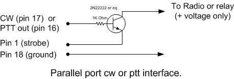
| LPT pin | Function |
| 1 | Strobe |
| 16 | PTT output |
| 17 | CW output |
| 18 | Ground |
For hints on diagnosing problems with a parallel port, see the note under Additional Parallel Port Interfacing just a bit further on.
Serial (COM) Port
When a serial port is used for CW and/or PTT keying, it is the RTS and DTR lines that are used.
| DB9 pin | DB25 pin | Function |
| 7 | 4 | PTT output (RTS) |
| 4 | 20 | CW output (DTR) |
| 5 | 7 | Ground |
The CW and PTT lines for a radio must be on the same serial/parallel port.Example: When COM4 is the CW Port and Radio 1 or Both is selected, PTT control for Radio 1 must also be on COM4. USB-to-serial converters are supported, but USB-to-LPT (parallel) converters are not.
Using a transistor
The keying circuit for serial port CW or PTT keying is similar to the circuit used with a parallel port.
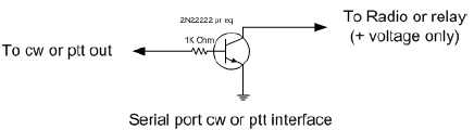
- Equivalents for the 2N2222 are 2N3904, BC547 or BC548.
- NB. It isn’t a bad idea to add a 1 kOhm resistor from base to ground, also adding a shunt capacitor of 10 nF is highly recommended at the collector output to ground in order to prevent RF feedback to base and subsequent blocking.
Using an opto-Isolator (opto-coupler)
Some users prefer to use an opto-isolator rather than a transistor, in order to provide more protection for the serial port in the event of something going wrong downstream. In that case, however, two special considerations may apply:
- You may need to place a diode in series with the input of the opto-isolator, to protect it from negative voltage swings on a standard serial port. Check the specifications of the opto-isolator you use to determine whether this is necessary.
- Some opto-isolators may not pull their output “low” enough (close enough to zero volts) to switch PTT or CW on a given transceiver. In that case, appropriate “pull-down” measures must be applied.
USB Port Keying
Not all computers have serial ports any more, or even if they do, there are not enough to control transceivers, packet, serial CW keying etc. In this case consider a USB-to-serial port adapter. Most of them do nicely for basic radio control functions and/or for CW and PTT keying. These devices require drivers within the computer; make sure that drivers for your operating system are available before trying to use one of these adapters.
The timing of serial port or parallel port keying can be subject to “stuttering” caused by the CPU being unavailable to control the port while it is busy with other tasks. For perfect CW not dependent on Windows processes the usual answer is to use a Winkeyer by K1EL. The computer communicates with the Winkeyer using normal ASCII characters via the serial port, which are buffered inside the Winkeyer and converted to CW there. The CW timing is thus independent of computer processing delays. A USB/serial adapter will work fine with a Winkeyer; in fact, most Winkeyers delivered today are WKUSB keyers with a USB-to-serial adapter built in to the keyer. Check the Winkeyer manual for more information.
In some cases PTT and CW keying may unexpectedly stop working when using a USB-to-serial converter, because Windows has shut down the USB port to save power. Check this Windows setting:
- Control Panel; System Icon,
- Hardware Device Manager Tab or button.
- Expand USB Serial Bus Controllers
- Highlight each USB Root Hub or Generic USB Hub in turn
- Double click for Properties settings, Power Management tab
- Remove the check mark from ‘Allow the computer to turn off this device to save power’
- The box is checked by default in most cases
- Repeat for every USB Root Hub and Generic USB Hub
- Reboot the computer
Another overview of serial- to-USB converters can be found at the RTTY contesting page by AA5AU at: http://www.rttycontesting.com.
Additional Parallel Port Interfacing
If the type of CW port chosen is LPT1, LPT2 or LPT3, and a hardware LPT port is used, additional information will be present on the chosen parallel port. In the Configurer, select the radio that corresponds with the selected port (Radio 1 or Radio 2). The BCD data on the LPT is that of the current active radio/VFO. The band data is available on multiple LPT ports — Radio 1 on LPT1, Radio 2 on LPT2 and so on. USB-to-LPT converters are not supported.
LPT pin and Description
1 Return for PTT and CW output. This pin has limited sink capability, so you may need to buffer it
2 Band output (Least Significant Bit) set by Antenna tab in Configurer. This pin is also used to stop the message sent on the hardware DVK.
3 NA-compatible TX focus. – Radio 1/2 Pin 3 will go to a logic LOW level (0V) when Radio 1 has TX focus and to a logic HIGH level (5V) when Radio 2 has TX focus. (NB. LPT pin 3 is the complement of Pin 14). Set ONLY if no hardware DVK output is selected (msg# 1).
4 NA-compatible RX focus. LPT Pin 4 will go to a logic LOW level when Radio 1 has RX focus and to a logic HIGH level when Radio 2 has RX focus. Set ONLY if no hardware DVK output is selected (msg# 2).
5 (Shift+singlequote) to toggle for Stereo mono. LPT Pin 5 will go to a logic LOW level for mono audio and to a logic HIGH level for stereo audio. Set ONLY if no hardware DVK output is selected (msg# 3).
6 Set ONLY if no hardware DVK output is selected (msg# 4).
7 Band output set by Antenna tab in Configurer
8 Band output set by Antenna tab in Configurer
9 Band output (Most Significant Bit) set by Antenna tab in Configurer
14 Radio select A/B (transmit focus) for DX Doubler compatibility. LPT Pin 14 will go to a HIGH level when Radio 1 has TX focus and to a LOW level when Radio 2 has TX focus. (NB. LPT pin 14 is the complement of Pin 3)
15 Footswitch input port
16 PTT output, high = transmit mode
17 CW output
18 – 25 Return for Band output
Diagnosing Parallel Port Problems
Will all PCI-e Parallel Port Cards Work?
As fast as technology moves, it is difficult to be categorical about this, and there has been some traffic on the reflector suggesting that some families of LPT port chips are not compatible with the software components used by N1MM Logger+ to control individual lines on an LPT port. Experimental results show, however, that two families of chips do work, as of February 2013: These chips are used both in single-port cards and in combination cards (2 serial and one parallel, for example), but have only been systematically tested in the one LPT port variant.
- MOSChip Semiconductors series MCS9900. This company is now owned by Asix Electronics Corporation,. and the very latest driver can be downloaded here. Specify PCIe Bridge for the product family. These chips are used in the SYBA SD-PEX10005 1 Port Parallel Card, available from the usual online sources.
- Oxford Semiconductor OX16PC952-954. This company’s chips are used in several 1-port LPT cards, including the StarTech.com PEX1P, which also is widely available. Originally, they were thought to be incompatible with parallel port switching, but this does not appear to be the case (contact N4ZR for details).
Diagnosing LPT Port Issues
Recently, a number of users have encountered difficulty using PCI-e LPT ports to control band decoders, SO2R controllers, and other devices. After a great deal of experimentation, here are a few things to try if you have trouble.
- Make sure you have the correct address specified in N1MM’s Configurer. Typically, PCI-e add-in cards seem to have I/O addresses that are not the standard ones for a given port number. For example, built-in LPT1 ports typically have an address of 0378 for our purposes, which is the lower of the two I/O addresses given for the port in Device Manager. On the other hand, 3 different PCI-e cards tested all have fixed I/O addresses at D000 and D010, regardless of the LPT port number, and the correct address is the higher one – D010. When in doubt, try them both.
- The first time you run N1MM Logger+ after a new installation, don’t run it from a shortcut. Instead, go into the N1MM Logger+ program directory, right-click on the executable (.exe) file, and select “Run as Administrator”. It has been suggested that this step may be necessary in some cases, in order for the component that drives the parallel port to be registered properly, and it can’t hurt. This is a one-time only step.
External DVK Interfacing
When you select DVK on a parallel port, antenna selection via that port is disabled, because the DVK pins and the antenna pins on the LPT port overlap. Following is the table of pin-outs for external DVK control:
F1 pin 3
F2 pin 4
F3 pin 5
F4 pin 6
F5 pins 4 and 6
F6 pins 4 and 5
F7 pins 4, 5, and 6.
When F1-F7 are pressed, a 100 ms. pulse is sent to the relevant pins for external DVK control.
In order to record messages on an external DVK, you will need to connect your microphone to it directly, and follow the procedure outlined in the DVK manual; N1MM Logger+ support is limited to triggering the first 7 memories when the corresponding Function Key (F1-7) is pressed, and stopping stored message playback when the ESC key is pressed. Some external DVKs have as few as 4 memories, in which case only F1-F4 will trigger playback.
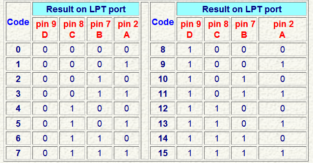
Band Decoder Output
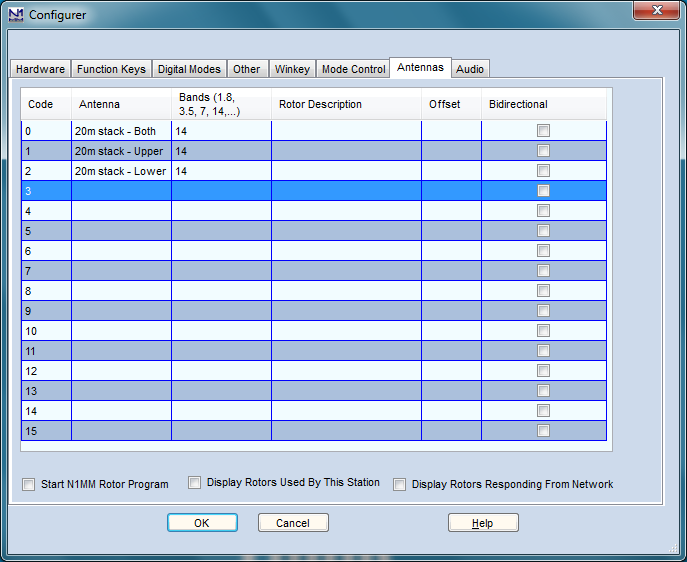
Pins 9, 8, 7 and 2 can be set using the Antenna tab in the Configurer. The output on the pins will follow the selected code which is being set up by the selected antenna.
Sample configs
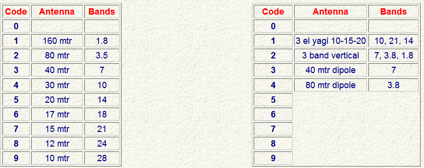
To replicate the default Top-Ten Devices behavior, you would need to set up the Antenna tab in Configurer as shown above to the left|
It is possible to use more than one antenna per band with N1MM Logger+. With Alt+F9 it is possible to toggle between these antennas. List the bands for each antenna with a comma separating them – e.g. 3.5,7
Sample Config > Antenna for two stacked antennas
You will need to make appropriate provision with a diode matrix on the output of your band decoder to select the appropriate antenna or antennas when a given code is sent from the program to the decoder. For example, if your band decoder outputs positive voltage and you use a tri-band beam with a single coax feedline, you will need diodes to sum the three signals from your band decoder into the one feedline.
Bearing Data
Bearing data for rotator control is currently not available on the LPT port.
Sound Card Interfacing
Of course, you can always use one of the many commercial audio interfaces designed primarily for digital modes. However, if you have a sound card that permits feeding microphone input through it to the line output (most do), and has a mixer that will allow you to independently set the level of the microphone, .wav playback and internally-generated audio (such as for AFSK), you really don’t need an interface at all. On SSB, simply plug your microphone into the sound card mike input. Cable the sound card’s Line Out to the Line In or Phone Patch input of your transceiver, and you’re done.
You may encounter hum, resulting from difference in AC potential between the chassis of your computer and that of your transceiver. In that case, a 600-ohm isolation transformer in the cable between sound card and transceiver is the cure. Another approach is to bond the transceiver and computer chassis together with a heavy wire. Many people do both.
If you absolutely must feed the audio output of your sound card into the microphone jack of your transceiver, the level will be far too high. In that case, a simple 10:1 resistive voltage divider is the solution, placed in the audio cable before the microphone jack.
In Windows 10 and 11, starting some time in 2018, there is a Privacy setting in Windows that must be set correctly to enable applications, including N1MM Logger+, to gain access to sound card inputs (e.g. for recording received audio or for decoding digital modes). In the Windows Settings window, choose Privacy, then from the areas on the left side of the window, select Microphone. An option should appear called “Let apps use my microphone”. Set this to On. Starting with the Spring 2018 release of Windows 10, Windows interprets this setting to apply to all sound card inputs, not just to the default microphone input.
Serial and Parallel port interfacing under Windows XP/ Vista/ 7/ 8/ 10/ 11
Windows XP, Vista, 7, 8, 10 and 11 require a special dll which will be installed automatically by N1MM Logger+ to use the parallel ports.
Exposing and Deleting Phantom Serial Ports
Unlike N1MM Logger Classic, N1MM Logger+ can support serial ports numbers up to 99. The following procedure is not likely to be necessary, but you may still wish to use it to eliminate “phantom” (not used, but unavailable) serial ports from your system,
Here is how to have Device Manager expose and remove invisible serial port assignments:
- Click on the Start button and select All Programs > Accessories.
- In Windows XP, Click on Command Prompt; in Windows Vista, 7 or newer, Right-click on Command Prompt and select the Run as administrator menu item.
- Type set devmgr_show_nonpresent_devices=1 and hit the Enter key.
- Start Device Manager. There are many different ways to do this; one is to right-click on Computer (or My Computer), select Properties, and then click on Device Manager. Another is to find Device Manager in the Control Panel.
- In the Device Manager window, select the View > Show Hidden Devices menu item.
- Click on the + sign next to Ports to see the full list of COM ports that have been assigned in your computer.
- Highlight an unused port number you wish to remove from the list and then press the Delete key. Accept when asked to confirm and continue with any more port numbers that you wish to delete.
Thanks to KK1L and N7WY for this tip.
Hooking up a Footswitch
A footswitch can be hooked up to a serial port or a parallel port. The footswitch program action is the same for both LPT and COM ports, i.e. footswitch closure causes the action selected in the Configurer for that port.
Parallel port
If pin 14 is not used to switch radios using an external SO2R box (for example, by using the Pause key), then hooking up a footswitch to LPT1 can be done by connecting a 10k resistor from pin 14 to pin 15. Pin 14 is normally +5V and provides pull-up voltage for pin 15.. Then connect a normally open footswitch between pin 15 and pin 18 of LPT1. Closing the footswitch pulls pin 15 low and performs the function selected in the configurer.
If pin 14 is being used for Radio A/Radio B control of an external SO2R box, a 5V supply with a 10k series resistor can be used to provide the pull-up voltage for pin 15.
Serial port footswitch information (using the 9 pin connector numbers)
Connect a 10k resistor between pin 6 and pin 7. Set DTR, pin 4 to “Always On” and RTS, pin 7 to “Always Off”. Connect the footswitch between pins 4 and pin 6.
The program action will be on footswitch closure. The footswitch wires can not be referenced or connected to ground.
Avoiding RFI and Other Common Interfacing Maladies
More often than not, reports of quirky, intermittent issues with radio control, CW and PTT interfacing, as well as hum and distortion in sound card audio, wind up being traced back to RFI – your own signal turning up where it doesn’t belong, or to improper grounding.
While we can’t afford the space to deal exhaustively with this topic, there are several good resources – the RFI reflector (RFI@contesting.com), this paper by Chuck Counselman, W1HIS, and these papers by Jim Brown, K9YC
USB Interface Devices
With the disappearance of serial and parallel ports on most new PCs, most N1MM Logger+ users are now forced to use USB interface devices to accomplish functions formerly performed using serial and parallel ports. These include consumer-grade USB-to-serial adapters as well as devices designed and manufactured specifically for amateur radio use. For the most part, with the help of software drivers installed when the device is first connected to the PC, these devices are configured in N1MM Logger+ as if they were true serial ports, with some important caveats and exceptions noted in the following sections.
A separate category of USB devices is the “USB Sound Card”, which are similar in function to on-board and bus-based sound cards except that its interface with the PC is through a USB port. Some devices aimed at the amateur community combine USB sound cards and USB-to-serial adapters in a single box. Some transceivers are now delivered with such USB devices incorporated internally. Generally speaking, once the appropriate drivers have been installed, these devices are configured in similar ways, regardless of whether they are in a transceiver or in a separate box or boxes.
USB-to-parallel adapters will not work for keying CW or controlling PTT through the standard parallel port interface, because these adapters do not permit controlling individual lines.
The only exception we are aware of is the SO2RXLAT by Piexx, which is designed specifically for this purpose.
CW issues with USB Adapters
N1MM Logger+’s serial and parallel port CW options are a simple and easy way to generate CW, but if your computer is slow, you may find the CW is not always smooth, particularly when receiving spots from a Telnet cluster in a busy contest. If this happens with serial keying, try using a parallel port if you have one. If you don’t, or if you want to put an end to CW issues once and for all, the answer is K1EL’s Winkeyer USB, which handles CW and all-mode PTT by offloading these functions from the computer entirely. It is also an excellent stand-alone keyer with 4 built-in memories.
Another issue can be poor weighting when using serial port keying. Some adapters have a lot of latency and will mangle your CW. Usually this can be corrected by finding a better driver for the adapter. Make sure you are running the latest vendor-provided driver for your operating system, not the one the OS picks. Some adapters allow you to set the latency in control panel.
General Comments on USB to Serial I/O Interface Devices
There are three different problems that are often encountered by N1MM Logger+ users trying to use USB-to-Serial adapters.
The first is loss of communications due to Windows powering down one or more USB ports. This problem and the solution are covered in this section.
The second of these problems relates to the specific chipsets and drivers used in these adapters. The market for these adapters is dominated by two chipsets, called Prolific and FTDI. There is a potential problem with adapters using the Prolific chipset for serial communications (in particular, for rig control) from N1MM Logger+. This problem only applies to actual serial communications; simple on-off keying of DTR and RTS for CW and PTT keying is not affected. There are several versions of the Prolific chipset (including counterfeit knock-offs), and also several versions of the drivers, and at least some of these drivers are incompatible with the Microsoft library routines used by N1MM Logger, DXLab Suite, Logger32 and some other amateur radio programs. The symptom is an error message with the error number 8020. The result is that with some combinations of Prolific chipset and/or driver software, adapters using the Prolific chipset may not work properly for rig control and similar purposes with N1MM Logger+. Rather than attempting to list all of the possible combinations of chipset version, driver version and operating system in order to determine which ones work and which ones do not, our simplest advice is to avoid using USB-to-serial adapters using the Prolific chipset for rig control, rotor control or similar serial communications purposes.
The third problem relates to FSK RTTY keying from MMTTY. MMTTY can use a true serial port for FSK keying, by programming the port to send 5-bit characters at 45.45 baud. Unfortunately, most single-port USB-to-serial adapters, or at least those that are new enough to work with Windows 7, cannot go slowly enough to do 45.45 baud Baudot. Some multi-port adapters (two or four serial ports from a single USB port, e.g. Edgeport) are capable of going slowly enough, but if there are currently-sold single-port adapters that can do direct FSK keying, they are few and far between.
The standard solution to this is to use EXTFSK (or EXTFSK64, on systems whose CPU is capable of supporting it). EXTFSK does all the timing internally instead of using the serial port hardware. EXTFSK is capable of keying FSK on any of the TxD, RTS or DTR lines on any serial port or any USB-to-serial adapter, and even on a true parallel port (but *not* on USB-to-parallel printer adapters, which are incapable of bit-twiddling). There is a downside to using EXTFSK – the timing is less accurate than the hardware timing from a true serial port. This may result in a slightly less readable signal under difficult conditions.
We are not aware of any USB-to-serial adapters that will not do FSK with the help of EXTFSK or EXTFSK64, nor are we aware of any USB-to-serial adapters that will not key CW or PTT on their DTR/RTS lines other than adapters that don’t have any physical connections for these control lines (such as the Elecraft KXUSB which does not implement the DTR and RTS control lines and therefore cannot use DTR or RTS).
Drivers: One key thing to never do is to allow Windows to tell you that it already has the driver for a particular device – you should always install the driver that comes with your interface. Windows can misidentify these devices when you plug them in and Windows will let you fail by using the driver it thinks is correct – and often Windows is dead wrong.
Generally speaking, with XP you can use most any USB to serial device (Prolific or FTDI chipsets) as long as you do not have a conflict. When it comes to Vista or Windows 7 and newer, FTDI seems to be the only game in town for close to sure results (Editor’s note – not all users agree with this characterization.)
Even with all of this, depending on what you have done with your computer previously, you may have problems. And again, the point of all of this is that the problems may have nothing to do with what hardware you are trying to use. It could be something left over by some earlier activity on your computer. That said, most installations of these devices goes well right from the start. When they do not, it can be very frustrating.
A further technical note, posted on the N1MM Logger reflector by Joe, W4TV, concerns an easy way to tell whether a given adapter can handle 45.5 baud RTTY:
Windows serial drivers set the data rate (baud rate divisor) with 14 bits of a “double word.” That limits the max/min range of the driver/UART to 214:1 … and any maximum rate higher than 512K will preclude operation at 45.45 bps.
The lower rates are not a 100% guarantee of compatibility but the higher rate is a certain sign that EXTFSK or AFSK will be required for RTTY.
Sound Interfacing and USB External Sound Cards
If you want to record your contest QSOs, or use stored messages in phone contests, you will need to interface your computer to the audio system of your transceiver.
This requires a little thinking ahead. If you wish both to record QSOs and to use stored messages, then you will need a sound device (be it internal or external) that has both Line and Microphone inputs, and that is capable of duplex operation – that is, it can both record and play back at the same time. This is not a rare capability, or something found only on expensive sound cards, but something to check in choosing which card to buy.
A more common problem, these days, seems to be sound cards – particularly those integrated into laptop computers – that have only a single input that can be used for either Line or Microphone, but not both at the same time. In those cases your best bet may be to get an external USB sound card. Again, it is not necessary to go high-end for this application, so long as both criteria above are met.
Two external USB cards that have been tested with N1MM Logger are the Encore, sold by NewEgg here .for under US$20, and the GWC, also sold by NewEgg at this URL for about the same price.. The ByteRunner UA-580 also works fine. (Thanks, Joe W4TV for this info)
Supported Hardware
Windows and External USB Peripherals
One word of caution about external (USB) sound cards … and other USB peripherals.
Windows can only address the “USB root hub” … they are directly connected to the internal PCI bus. Windows will process data from all “Root Hubs” in a machine in parallel. However, all of the “child” devices are like leaves on a tree, each leaf which “grows” from the same “root” receives a time slot (generally 16 msec) in turn. If you have too many “leaves” on one root hub, the delay can become excessive and result in communications failures (time outs) with the controlling software (Logger).
This can be particularly problematical with some software that polls every 50 to 100 msec and will timeout if a response has not been received before the next poll interval. USB can easily handle the aggregate throughput (it will do something like 240 mb/sec) but the delays can be a problem if the software writer does not account for them.
Be particularly aware of this issue if you use external hubs and add many devices – particularly devices like memory sticks and “thumb drives.”
73, Joe Subich, W4TV
Green Heron Engineering Inc. – GH Everyware (rotator control)
N1MM Logger can send bearing information direct to the Green Heron GH Everyware software. N1MM Logger must be configured to send rotor information over the network (using UDP packets). This can be done by editing the N1MM Logger.ini file. Information regarding this is given in the supplied documentation with the Green Heron software, which is bundled with Everyware Remote and Base hardware and not sold separately.
Please refer to the Everyware documentation for further details.
Ham Radio Solutions – EZmaster
EZ Master is an LPT port and USB Device that interfaces your PC with several devices in your shack like radios, antennas, filters switching, microphone, headphones etc. Including PHONE, CW, RTTY, DIGITAL Mode interface and internal DVK, CW Keyer and SO2R switching.
More information can be found on the Ham Radio Solutions website.
K1EL – Winkeyer
Winkeyer is an external keyer chip designed by K1EL and G3WGV, which combines full electronic keyer features with a serial interface to a computer. Winkeyer is intended to interface with compatible Windows software and produce CW from ASCII characters sent to it, avoiding CW timing problems caused by multitasking.
N1MM Logger was one of the first Windows logging program to support Winkeyer, and it has become a favorite CW solution for N1MM Logger+ users. Serial or parallel port keying may work fine, particularly with faster computers, but using Winkeyer can enable you to get by with a slower machine or run other programs in conjunction with N1MM Logger+, while keeping your CW perfect. Stand-alone keyers are available, and the Winkeyer keyer chip is also used in multi-function interfaces such as Ham Radio Solutions EZMaster, RigExpert, and several microHAM interfaces.
More information can be found on K1EL’s website.
A full explanation of setting up N1MM Logger+ to work with Winkeyer is found in the Configurer section of the N1MM Logger+ Manual.
microHAM – microKEYER
The authoritative source for information on configuring N1MM Logger to work with various microHAM products is the microHAM web site which offers a variety of “Example Configurations”. These configurations are also accessible through the Help menu of the microHAM Router software, under “Document Download.”
Tentec ORION + “Mute mic on supported radios”
In the Configurer dialog, Other tab, make sure that “Mute mic on supported radios” is *NOT* checked. If that is checked, the Logger mutes the microphone and turns on the AUX input during DVK operation. By design the microKEYER routes DVK audio to the microphone input.
ICOM CI-V Interfaces + Transceive on/off Features
How to connect microHAM devices to N1MM Logger+ together with, for example, a SteppIR antenna which needs Transceive ON to know the radio frequency while N1MM Logger+ likes to see Transceive OFF.
- connect all of the CI-V devices in parallel (tip to tip, ground to ground)
- turn off Transceive in the Icom rig
- turn ON “polling” in microHAM Router
- turn OFF “polling” in microHAM Band Decoder
The microKEYER (Router) will poll only when the logging software is not polling (for example, Router will poll even though N1MM Logger+ does not). The Router polls will keep data flowing on the CI-V bus to allow the SteppIR and other similar hardware to stay “in sync.”
The microHAM Band Decoder will provide antenna switching (including support for multiple antennas per band with the appropriate external switch) according to your normal programming , provide drive for bandpass filters (several brands) and can do “format conversion” which will allow a Yaesu (Quadra, FL-7000) or Icom (IC-2KL, IC-4KL, IC-PW1) solid state amplifier to work with any other (supported Yaesu, Kenwood, Icom, or TenTec) radio.
The same capability exists with non-Icom radios.
N1MM Logger+ can’t read the RX frequency (shows as 0) – frequency shown fine in microHam router without the Logger
N1MM Logger+ polls for slightly different data than Router (VFO A and VFO B vs. “Current operating frequency”) so Router “times out.” Solution:
Open Router | Control | Set and uncheck “Disable router queries” .
Truncation of Messages (When Using Winkeyer Keyer)
Symptom: Sends all the macro CW messages except the last letter and then goes back to receive. The solution is to add a space or the | character (the shifted \ character) at the end of the macro message. The | character is about 1/3 of a space.
microHAM – MK2R/MK2R+
- To set up MK2R+ with N1MM using LPT control see: http://www.microham.com/Downloads/MK2R_N1MM_Setup.pdf
Q. When I load N1MM logger the message shows: “Winkeyer v2 detected, Only Winkeyer v4 and higher are supported in N1MM.”
A. That’s a Winkeyer initialization error of some kind which shows when the MK2R+ is not switched on when N1MM logger is started.
Q. How many serial ports are needed by MK2R to fully work
A. In any case, one only needs five ports for a fully functioning system with N1MM (Radio 1, Radio 2, PTT 1, PTT2, and Winkeyer). Any other functions (Packet, rotor control, etc.) do not need
to be in the “first eight.” MMTTY/Digital Interface will share a port with PTT (and CW if you are not using Winkeyer) … and MMVARI or MMTTY in AFSK mode does not require a port at all. Even if/when the SO2R control signals get mapped to serial handshake lines or the software adds support for the microHAM control protocol (on a virtual port) one additional port will not push most systems “over the line” – although the ability to start the block of eight other than at COM1 would provide a bit of insurance.
73, Joe, W4TV
An example setup
microHAM Router
- VOICE Audio Switching for both radios: CmCmCm
FT1000MP, Proset Plus plugged to front mic jack.
N1MM Logger (6.10.9 or higher)
- Configurer >Audio tab
- 2 – Single Card – Two Radio, No sound card SO2R
- Select Device = USB Voice CODEC
- Select Input Line = Microphone
- Select Line to Mute = Microhone
- Recording bits = 16
- Sampling rate = 22050
Ctrl+Shift+Fx to record, Fx to playback.
USB-only SO2R Support
With USB-only SO2R support using the the MicroHam SO2R protocol, an LPT port to command various SO2R functions with the MK2R/MK2R+ is no longer needed.
Designate a virtual COM port as your MK2R control port in N1MM logger. To do this, check the CW/Other box for the port, click on ‘Set’, and check the MK2R box on the port details dialog. Then go to the SO2R tab on the MicroHam Router, select Microham SO2R protocol with the “radio button”, and identify the COM port in the drop-down list just below. Finally, if you want to use program-derived band data, on the ACC tab change the Radio 1 and Radio 2 options to “SO2R protocol controlled”. If you want to control band decoders for two radios, you may need to wire up a new cable to get Radio 1 data from pins 6-9 on the ACC connector, and Radio 2 data from pins 10-13.
Record-on-the fly within the program is supported using USB-only.
Suggested Port Setup by Joe, W4TV
“The MK2R/MK2R+ operates very well with six total ports (I will use A – F to avoid particular numbers):
MK2R/MK2R+ with 6 Total Ports
| Port | Connected device |
| COM A | Winkeyer (it is best to assign Winkeyer to the “lowest” port to avoid loss of CW if another port is activated for CW) |
| COM B | Radio #1 (PTT and Footswitch is optional on this port) |
| COM C | Radio #2 (PTT and Footswitch is optional on this port) |
| COM D | Digital #1 FSK and PTT for Radio #1 (assign Radio 1) |
| COM E | Digital #2 FSK and PTT for Radio #2 (assign Radio 2) |
| COM F | MK2R (protocol port) |
A user who does not choose to do FSK (uses AFSK only) can survive with FOUR virtual ports as PTT can be enabled on each of the radio ports – even with radios that normally expect “handshake” – as the MK2R does the handshaking and frees both RTS/DTR lines for control functions.”
The COM D and COM E PTT settings (or the optional radio port PTTs) are necessary if you wish to use the built-in N1MM Logger “DVK” with PTT (rather than VOX). This does not mean that you have to designate COM 5 and 6 on the Ports tab as PTT – instead you can just make sure the PTT box is checked on your two FSK ports in Router. If you wish to use the MK2R’s built-in DVK instead, you will need to check the “DVK” box on the port you are using for the MK2R.
On-the-Fly Recording from within N1MM Logger
In order to make on-the-fly recording with Ctrl+Shift+Fx work with N1MM and the MK2R+, there are a couple of unusual requirements:
- if using the MK2R SO2R protocol (USB-only), you need to use MM 7.10.9 or later
- If your computer uses the Realtek or Soundmax chips for its on-board sound, then you will need temporarily to set the USB Voice CODEC to be the default sound device in Windows and be sure to turn off all Windows sounds for the duration, also in the Control Panel. There’s a glitch in the Realtek/Soundmax drivers that doesn’t let mic audio get through to the MK2R+’s USB Voice CODEC (which it uses to record and play Function Key messages) unless you do this.
RigExpert
When installing drivers for RigExpert Std or Plus, it creates 4 virtual COM Ports on your computer along with USB Audio Codec (for its internal sound card). Some users of the RigExpert TI-5 interface have reported that the 4th virtual port, for FSK keying, does not work with MMTTY. It is still possible to key FSK RTTY, using the 2nd virtual port (PTT/CW/SoftFSK) using the version of EXTFSK supplied with the RigExpert, and configuring MMTTY to use EXTFSK.
Click on “Show Serial Ports” (ListRE program which comes with RigExpert software) and write down COM port numbers for CAT and PTT/CW for future reference.
Then run your N1MM. (Make sure you are not running other logging programs at the same time to avoid port conflict).
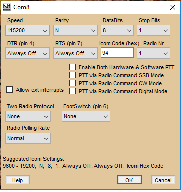
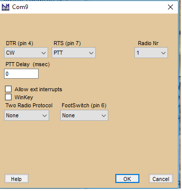
Go to Configure and click on Configure Ports, Telnet Address, Other. Click on Hardware. You will see a selection of COM port from COM 1 to COM 8. Select the proper COM port number for CAT (the one you memorized before), select your radio model and in Details select the proper parameters for your radio (baud rate, etc.). Then select proper COM port number for CW/PTT (check CW/PTT) and in the details set DTR to CW and RTS to PTT. If you are using RigExpert Plus, then you may also set a separate COM port for Winkeyer.
If you want to use RigExpert as your Sound card (for SSB messages or RTTY) you may go to Audio (under the same Configurer menu) and select USB Audio Codec as you Sound Device.
Don’t forget that you can not run two programs that use the same USB Interface at the same time.
If you have older RigExpert – SD or 2.2, you still may use it with N1MM, just need to install additional driver (REAUDIO).
When RigExpert SD is used with N1MM for Voice Keying, in the Configurer’s Audio select “RigExpert” as a Device. Then configure the Recorded wav file path in the “Files”.
The older RigExpert models,need to have REAUDIO installed. For newer RigExpert models REAUDIO is not needed “USB Audio Codec” in the “Select Device” menu should be seleceted.
Top Ten Devices – Band Decoder and DX Doubler
To replicate the default Top Ten Devices behavior, you would need to set up Configurer >Antenna tab as shown in the Interfacing section.
Hardware Update: ‘Both Ears on the Inactive Radio’ versus ‘Both Ears on the Active (or Run) Radio’ from the Keyboard
I wanted to go one better and mimic the “PTT” operation of the DXD, which puts both ears on the INactive radio for aggressive S&P, but still be able to put both ears on the Active (or Run) radio from the keyboard, to help pick up weak answers to my CQs while HC8N is blasting on the S&P radio at S9 +40. You can do this manually by switching the DXD audio mode switch from PTT to Auto, but I’d rather keep my hands on the keyboard.
After corresponding with George, W2VJN and Dave, N3RD, of Top Ten, and entirely thanks to them, I have it working. I also owe a vote of thanks to Terry, N4TZ/9, whose article in September/October NCJ describes modifying the DXD to do the same trick, but with a footswitch, and got us all thinking.
First, put the DXD jumpers (2) in their CT/Writelog/TR/MM position. This has the effect of isolating pin 5 of the LPT port. Then put a 2N2222 open collector switch between pin 5 and the Auto terminal of S3 on the DXD (that’s the audio mode switch). Specifically, pin 5 drives the base of the transistor through a 1K resistor connected to the high side of R22, just like the basic CW keying interface. The emitter is grounded to the ground side of R22, and the collector is wired to the switch side of R29. I mounted the transistor next to R22 with double-sided tape. Ugly but effective. That’s all there is to it.
When using the DX Doubler on a port other than LPT1 check out the proper addresses.
73, Pete N4ZR
West Mountain Radio – RIGblaster
CW and Digital Setup RIGblaster Plus
Inside the RIGblaster Plus set the following jumpers on the P5 jumper block: D9 and D12, corresponding to RTS on PTT and DTR on KEY. Switch the port on which the RIGblaster is set from DIGITAL to OTHER. In N1MM’s configuration use DTR (pin 4) set to CW and RTS (Pin 7) set to PTT. Using this configuration, everything works properly generating CW from N1MM and furthermore, this combination will allow the other soundcard related things to work (MMTTY, SSTV, PSK, Voice Key Express, etc). (by David, K1TTT)
When your radio in CW stays in key down position try setting DTR to CW
SSB Setup RIGblaster Plus
- Serial port setup (configurer)
- Com2 (any com port will do)
- DTR: Always OFF
- RTS: PTT
- On the RIGblaster itself
- Set the Tx/Auto switch to Auto.
- Sound Volume Level
- Use your soundcards volume control
With it set up this way, it correctly mutes the microphone while transmitting a wav file and the VOX works when not transmitting a wav file.
RIGblaster Advantage
A number of our users have experienced difficulty setting up the RIGblaster Advantage to do various modes. The following is based on information from West Mountain Radio’s support department, but any errors are ours alone.
When you load the RIGblaster driver onto your computer (we won’t document that process here, because it is well covered in the Advantage manual), you will see a new virtual COM port and a new USB Audio Device reflected in your computer’s Device Manager. Make note of the COM port’s number
The virtual COM port can be used for PTT using RTS), CW or FSK (using DTR) keying, and control of your radio. The USB Audio device (called “RIGblaster Advantage Audio” in Device Manager) has both playback and record channels, and can be specified anywhere you are asked to specify a sound card.
Control of your radio is available from the Advantage in one of two forms – an RS-232C level DB-9 connector, and a TTL level 3.5mm stereo jack. The TTL jack (labeled CTL IN/OUT) is suitable for controlling radios that use TTL-level control – such as Icom’s CI-V remote jack and the 8-pin mini-din CAT jack found on some Yaesu models. It is not suitable for driving older Kenwood radios which employed a “negative TTL” scheme (such as the TS-440S and TS-850). Your best bet in this case is to buy or build an adapter to convert the Kenwood control setup to basic RS-232.
The Advantage’s RS-232 port can drive many RS-232C equipped radios with one proviso – the transceiver must not require hardware flow control. Otherwise what happens is that the radio holds RTS high and the Advantage will be stuck in transmit.
Many Yaesu radios have a menu option “CAT RTS” which can be disabled – this will get CAT working on those radios with just a straight serial cable between the Advantage and transceiver.
The FT-847 actually requires a null-modem cable but this is the only radio WMR knows of which does. Because the FT-847 does not require flow control this works fine with the Advantage.
Kenwood radios without the ability to disable flow control require a modified serial cable which shorts RTS/CTS at the radio end, to fool the radio into believing flow control is active. This works in practice on most radios we have tried it with, but has not been tested with N1MM Logger. A more elegant solution is just to use a separate USB to RS-232C adapter cable, giving you a second virtual COM port in Windows which is dedicated just to radio control. In this configuration, the Advantage COM port is used only for PTT and CW keying.
The Advantage has a 3-position toggle switch on the front panel to determine how PTT is handled. In the “COM” position, PTT is under the control of the RTS line of the Advantage’s virtual COM port. The center position, “OFF”, disables PTT and CW through the Advantage. The third option is “VOX”, which is derived from the audio signal itself in phone and data modes using AFSK.
Remember that if N1MM is configured for PTT by radio command, the Advantage has no way of knowing this and will not go into transmit even though the radio does. Always make sure that PTT is done by RTS if under serial port control, or use the VOX position if using PTT via radio control.
In summary, most radios can be set up for PTT (using RTS) and CW/FSK keying (using DTR). As long as the radio has either an 8 pin round mic jack or an RJ-45 mic jack it will work, because this is how audio and PTT get to the radio. For many radios, CAT can be achieved with a simple cable. For radios equipped with RS-232C jacks and which insist on flow control it is probably just simpler to use a separate USB to RS-232C cable.
Setting Up N1MM Logger with the RIGblaster Advantage
Now we get to the easy part. Go to Config > Configure Ports. Open the hardware tab.
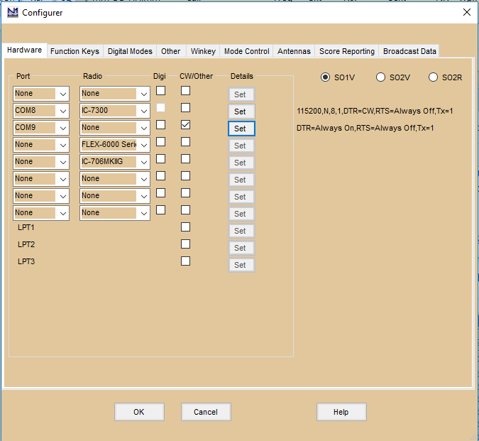
Select the virtual COM port number you will be using for radio control. Select your radio from the drop-down list. Click “Set”. Do not select PTT via Radio Command. Make sure the communication parameters match between the program and your radio (found in its manual). If you are able to use the same COM port for all functions (rig control, CW and PTT all on the same port) and do not need the RIGblaster’s own CW/PTT interface, then set DTR to CW and RTS to PTT (if needed), check the CW/Other box and you’re done.
To configure the RIGblaster Advantage’s COM port for CW/PTT, select the Advantage’s COM port and check its CW/Other box. Click “Set” for the Advantage’s COM port. Set DTR on that port to CW, and RTS to PTT (if needed). Typically the radio will require hardware PTT, radio command PTT, or the radio’s VOX to be enabled.
Transverters
N1MM Logger+ has transverter support in the form that per bandmap an offset frequency can be set. Right click menu bandmap and select Set transceiver offset frequency. Enter the transceiver offset frequency in kHz (minus is allowed). Example: 116000 when using a transverter from 28 MHz to 144 MHz (144000 – 28000 = 116000). The same for other bands (up or down). This can be set per bandmap so when using two transceivers with transverters they can each be on a different band. The offset is saved by the program so after a restart the offset is still there.
Other Hardware Information
All by Joe Subich, W4TV
USB Soundcards
The manuals for the soundcards below (in alphabetic order) indicate they have independent microphone and stereo line inputs.
- Audigy 2NX External
- Creative SoundBlaster MP3+
- Turtle Beach “Audio Advantage Roadie”
The “low price option” below does not have an on-line manual but the specs on the web site show separate mic and line jacks.
- Byterunner UA-580
- appears to be the recommendation for those who need an external sound card (laptop, etc.).
Other Soundcards
- SoundBlaster Live 24 External
- The one issue with the Live 24 External is that you cannot use the mic and line inputs at the same time (connecting the mic will disconnect the line). It will work fine for internal DVK in N1MM but you cannot “record QSOs” and use DVK at the same time if you loop the microphone through the Live! 24 External.
External versus Internal Soundcards
There are claims that External USB soundcards work substantially better (and should be used) than internal soundcards (on digital signals).
Joe, W4TV: The claimed “advantage” comes from flawed tests which fail to properly set the input level to each sound device to take maximum advantage of its dynamic range.
Except for the very worst sound cards or exceptionally noisy systems, internal sound cards have at least 60 dB of usable dynamic range (the better 16 bit cards have 80 dB of dynamic range and 24 bit cards with high level inputs can have dynamic ranges that approach 100 dB). If the audio from the transceiver is such that the receiver noise floor (no antenna) is six to ten dB above the noise floor of the sound card, the software DSP (MMTTY, etc.) will be able to operate at its full capacity. Receiver AGC, etc. will limit the receiver output to a level well below the input capacity of the soundcard. Most receivers will not vary more than 30 to 40 dB from quiet band to S9 +40 dB receive signals. Soundcard performance is not a matter of internal vs. external. It is a matter of careful attention to setting the proper level to allow the soundcard to function properly.
Unsupported Hardware – W5XD MultiKeyer
The W5XD MultiKeyer is not supported and there are no plans to do so. SO2R support is provided by sound cards and Winkeyer or by other external hardware using serial and parallel ports.
N1MM Rotator Control
Rotator control by N1MM Logger is supported using
- External software
- N1MM Rotor (comes with N1MM logger)
- PSTRotatorAZ (15 Euros/US$22 by Codrut Buda – YO3DMU)
- External hardware
- ARSWIN by EA4TX
- ERC and ERC-M by Rene Schmidt DF9GR – PSTRotatorAZ required for ERC-M to control two rotators
Rotators can be controlled in several different ways:
- Entry window:
- by entering a beam heading in the callsign field and press Alt+J. The rotor will turn to the entered beam heading
- Example:234 Alt+J will turn the rotor to 234 degrees
- The number must be numeric, ❯= 0 and ❮= 360
- using the menu items in the Tools menu
- Turn Rotor Alt+J – Turn rotor to bearing for the callsign in the Entry window
- Stop Rotor Ctrl+Alt+J – Stop turning the rotor when turning and no bearing in callsign field in Entry window
- using the short cut keys below:
- Alt+J – Turn rotor to bearing for the callsign in the Entry window or to the callsign in the callframe (when callsign field is empty)
- Alt+L – Turn rotor to long path bearing for the callsign in the Entry window
- Ctrl+Alt+J – Stop turning the rotor when turning and no bearing in callsign field in Entry window
- by entering a beam heading in the callsign field and press Alt+J. The rotor will turn to the entered beam heading
- Bandmap window: by right clicking on a spot and select: ‘Turn Rotor’
- Available Mult’s and Q’s window: by right clicking on a spot and select: ‘Turn Rotor’
- N1MM Rotor stand-alone program
Some remarks
- If there is a call of less than three characters in the callsign field in the Entry window nothing will happen.
- The status bar will show the bearing it will turn to. Example: Turning Rotor to 123 degrees
- Normally the rotor will turn to the country bearing after a callsign is entered. This info comes from the country file and mostly is the center of the country. In grid square contests however that is mostly not practical so when a grid is entered the rotor will turn to the calculated bearing between the own grid and entered grid square.
Rotator Control Basics
N1MM Rotor has the ability to control up to 16 rotors per station, and to control rotors connected to other computers on your LAN. Each rotator requires its own COM port, unless external interfacing software is used. N1MM Rotor leverages the Antenna tab to define what rotators are controlled when you are on a band. N1MM Rotor can even rotate a stack with one command. N1MM Rotor is an external program which can be used from within N1MM Logger or as a stand-alone program.
Supported Rotator Types
- DCU1 – No Stop button supported.
- M2 Orion – Speed shown to bottom right of status bar.
- Prosistel
- AlfaSpid
- Yaesu
- RC2800P-A
- Rotor-EZ
- AlfaSpid ROT2
- Prosistel C
- Green Heron RT-21 (use DCU-1 option or Rotor-EZ setting)
| All rotators except the DCU1 support position reporting. It would be worth trying the Rotor-EZ setting with other rotators that use the DCU-1 protocol or a superset of it, because the antenna position may be reported in the Rotor window. |
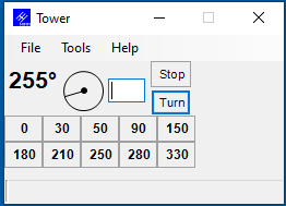
Upper pane: The upper pane shows the selected rotator (as entered in the Setup under Tools) and behind the @ the current rotator position.
Menu bar: Shows the File, Tools and Help menus.
The big digits indicate the current rotator position. When an antenna offset has been entered this will be shown in small digits to the right of the current rotator position.
More to the right a visual indication where the rotator is pointing. The line in the circle can be dragged to turn the rotator, for rotators that support position reporting.
The textbox is an entry field where you enter the bearing the rotator is to be turned to.
Clicking the Turn button will turn the rotator to that position, and the Stop button will stop turning the rotator at the current position.
A reverse offset will be shown as (R) .
Status bar: Shows the speed when reported by the rotator.
The program will be brought to top when turning (unless minimized)
File Menu Selections
- File
- Always on Top – Select to have the program always on top
- Exit – Exit the program
- Tools
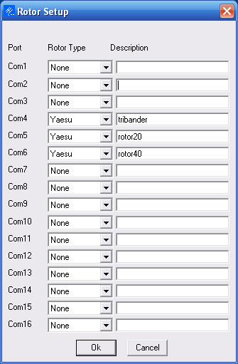
- Setup Rotors – a dialog named ‘Rotor Setup’ will be displayed as shown below
- Set Current Antenna Offset
- The offset is entered on the antennas tab of the Configurer, or can be entered for the selected rotor. This offset is added to the rotor position to determine the antenna position, so it should be entered with a “-” sign when the offset antenna is rotated clockwise relative to the rotator direction. This is useful for antennas that are mounted at 90 degrees for pattern interference reasons, or for antennas that have simply turned some in the wind over the winter
- Set Current Antenna Bidirectionality
- Bidirectional is for dipoles, or SteppIr’s where the user wants to reverse the antenna rather than turn it more than 180 degrees
- Calibrate Rotor – Calbrate the rotator. Only when supported by the rotator like the M2 Orion. The ERC/ERC-M hardware does calibration in firmware.
- Prosistel C Config
- A dialog will open where you can set the rotator stop to North or South and the delay of the characters
- Set rotation limits
- This feature is for owners of rotators with brakes that jam. You may enter a number which will restrict how close the rotator will be turned to 0 or 360 degrees. If you enter 10, the limits will be 10 to 350 degrees. Note that this can only be set for all rotators handled by an instance of the program. It didn’t seem worth adding it to the antenna tab
- A new line will be shown for every rotator that has been set up
- Each line represents a rotator as entered in the setup under Tools
Button and Mouse Assignments
- Manual entry field – Type a heading and press Enter or the Turn button to turn the rotator. The entered number is in degrees.
- Maximum: 450 and minimum 0. An error message will appear when entered otherwise when pressing the Turn button.
- Turn – Click to turn rotator to heading in textbox. Pressing Enter will also turn the rotator, if the entry focus is on N1MM Rotor.
- Stop Alt+S – Press to stop rotator turning. Pressing Alt+S or Escape will also stop turning the rotator.
- This button is only shown when the rotator supports this feature.
- F1 – F10 – Pressing the F-keys mapped to the bearing buttons will turn the rotator to the position as shown on the button. Right click to set the heading value.
- Bearing buttons (F1 – F10)
- Left mouse button click
- Pressing one of the bearing buttons will turn the rotator to the position as shown on the button.
- The F-keys F1 through F10 are mapped to the 10 bearing buttons.
- Right mouse button click
- Set Button to Current Position
- The heading as entered in the manual entry field will be used to set the position.
- Set Button to a Specific Heading
- A dialog will appear and a heading can be entered which will used to set the position.
- Set Button to Current Position
- Left mouse button click
Only rotators that report position will be able to show the current position (also when rotating).
Sending Rotor Position Information to N1MM Logger
By default, N1MM Rotor sends position information only to the N1MM Logger main program that is running on the same computer as N1MM Rotor. If you are using only one computer, with both N1MM Rotor and N1MM Logger running on that computer, you can skip the rest of this section, but if N1MM Rotor is running on a different computer from N1MM Logger, you need to read on.
If you want to send position information to copies of N1MM Logger running on other computers, you must use a text editor to manually edit the N1MMRotor.ini file in order to tell N1MM Rotor which computers to send the information to. Look for the line “RotorReportingIP” in the [Rotors] section; if it doesn’t exist, you will have to add it.
If all of the computers in the network are in the same subnet, i.e. they all have IP addresses that start with the same three numbers, such as 192.168.1.xxx, then you can send position information from N1MM Rotor to all of the computers in the network simply by setting RotorReportingIP to the broadcast IP address (last number = 255), as in:
[Rotors]
RotorReportingIP=192.168.1.255
If you only want to send position information to certain selected computers on the network, you can specify one or more individual IP addresses, separated by spaces. For example:
[Rotors]
RotorReportingIP=127.0.0.1 192.168.1.10 192.168.1.12
This will send rotor position information from N1MM Rotor to N1MM Logger running on three computers: the same computer that N1MM Rotor is running on, which is always denoted by 127.0.0.1 regardless of which subnet it is in, and two additional computers whose IP addresses in this example are 192.168.1.10 and 192.168.1.12. Other computers in the network whose addresses are not specified in the N1MMRotor.ini file will not receive the rotor position information. The IP addresses do not all have to be in the same subnet, but of course they must all be reachable from the computer that N1MM Rotor is running in.
Using N1MM Rotor Stand-Alone
Go into the N1MM program directory with Windows Explorer and find ‘N1MMRotor.exe’. This is the N1MM Rotor program. A shortcut on the desktop would be an easy way to start the program. All features mentioned above can be used.
Using N1MM Rotor with the Main N1MM Logger Program
Configure your rotors using the N1MM Rotor standalone program, as shown in the previous section. Verify that the rotors work correctly.
The N1MM Logger main program has the capability to turn rotors from the Entry Windows. To configure this capability in the N1MM Logger main program:
- Setup the antenna selections in the Configurer; Tab: Antennas
N1MM logger setup dialog in >Config >Configure Ports, Antennas tab
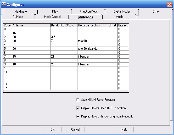
The alphanumeric name in entered in the Rotor Description in the Configurer Antennas tab, must be exactly the same alphanumeric name entered in the N1MM Rotor Setup form.
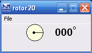
The N1MM Logger main program also has the capability to display the current direction of any rotor used by the controlling station, or any rotor in the network. To configure this capability, use the checkboxes “Display Rotors Used By This Station” and “Display Rotors Responding From Network” in the Configurer Antennas tab. A new display form will appear for each responding rotor:
When “Display Rotors Used By This Station” is enabled, only the rotors used by the currently active bands in the Entry Window(s) will be displayed. When you change bands, the displayed rotors will be automatically updated.
When “Display Rotors Responding From Network” is enabled, all rotors that report their position to the computer, from any N1MM Rotor running on the network, will be displayed.
To start N1MM Rotor automatically from within the N1MM Logger main program, use the checkbox ‘Start N1MM Rotor Program’ in the Configurer Antennas tab.
One Rotator Per Radio – how to do it
Occasionally, we get questions about how to relate a rotator to a specific radio or VFO, in SO2R – so that when you enter a callsign in that radio’s Entry Window, the rotator for that radio’s antennas receives the command.
The answer is simple – On the Antennas tab of the Configurer, define the antennas for the second radio as if they were alternative antennas for a given band, and specify the desired rotator’s COM port . Then, while the second radio’s Entry Window is active, hit Alt+F9. You only need to do this once, each time you change bands on the second radio. See this page for more on configuring more than one antenna for a given band.
N1MM Rotor running on another computer
Let’s assume that N1MM Rotor is on a separate computer which has IP address 192.168.1.14, and your computer, running N1MM logger, is 192.168.1.10.
- Make sure N1MM Rotor is running on the computer that has the rotor connected to it.
- Network the computers together.
- In the Configurer, Broadcast Data tab on the 192.168.1.10 computer
- Rotor =127.0.0.1:12040 192.168.1.14:12040
- Enable “Display Rotors Responding From Network” in the Antennas tab
- In the Configurer, Antennas tab on the 192.168.1.10 computer, each rotor must be defined in the table
- Put this in your N1MMRotor.ini file on the computer running N1MM Rotor (192.168.1.14):
- [Rotors]
- RotorReportingIP=127.0.0.1 192.168.1.10
- Control the rotator by menus in the Tools menu. You put the direction or a callsign in the call textbox and press Alt+J
- The requesting station will see a Rotor Form window open, showing the current direction of the rotator. Note that some rotators cannot report progress.
- You may need to change your firewall settings to allow rotor traffic between computers.
Turning a Stack
In the example picture above at the right the stack is on Com3 and Com4 and are turned at the same time when turning antenna 4 (stack).
Enter 3,4 and the heading selected will be sent to the rotor program and it will tell the rotators (of whatever type) on COM3 and COM4 to turn to that azimuth. If you want to control a single antenna, you will have to switch to that single antenna using the antenna toggle (Alt+F9) in the main program, press ALT+J and then toggle to the set of antennas that you want.
Run time error: 126
Run time error 126 could be caused by a firewall that doesn’t like a UDP message sent to 127.0.0.1 to notify the rotor program of what window is active. If you want to use the rotor program without getting this error, you will need to figure out what program is causing this interference. First check your firewall. If that is not it, one user found that a program called “Port Explorer” was the cause. When “Port Explorer” was closed, the problem went away.
Rotator UDP Packet Information
Broadcasts to operate the separate Rotator Control program are sent automatically when the user selects >Tools >Turn Rotor (alt+J), and do not require configuration settings or modifications to the N1MM Logger.ini file. The broadcasts are always sent on port 12040. Developer Note: the rotator packet lacks XML header tags and is not XML compliant. We know that and will not fix it because we fear breaking third-party routines written years ago.
The Entry Window >Tools >Turn Rotor command produces the following UDP message on UDP port 12040:
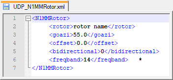
Note *: Examples of freqband encoding are 1.8, 3.5, 7, 14, 21, 28
The Entry Window >Tools >Stop Rotor (ctrl+alt+J) command produces the following UDP message on UDP port 12040:
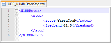
Note: the rotor may be specified with the name shown in the Rotor program setup dialog, or the number of the com port to be controlled (e.g. “3”)
Rotor status update messages sent from the separate N1MM Rotor program on UDP port 13010 are in this format:
rotorname@rotorheading
External Rotator Hardware and Software
Rotator control is supported directly by software and/or hardware from:
- ARS-USB by EA4TX
- PSTRotatorAZ (15 Euros/US$22 from Codrut Buda, YO3DMU) See the links section for urls.
Start your ARS-USB or PSTRotatorAZ software before attempting to control rotators.
The ERC-M rotator controller by DF9GR offers control of an AZ-EL rotator system or two azimuth rotators using a single COM port. However, this mode of operation is not supported by N1MMRotor at this time. You will need to use two linked instances of PSTRotatorAz as intermediary between N1MM Logger+ and the ERC-M. Setup is a little tricky but is fully documented and works fine.