The Configurer
Hardware Tab
The Configurer is our name for the tabbed dialog that appears when you click Config on the Entry Window top menu, and then choose Configure Ports, Mode Control, Audio, Other. The Configurer has many tabs with program settings influencing all aspects of the behavior of the program. Be careful in setting up items on the different tabs, to be sure that you understand that the option you are choosing is what you want.
Configurer settings are remembered by the program in the N1MM Logger.ini file, which is in the N1MM Logger+ user files area. Function key definitions, telnet clusters, call history, and country information are not saved in the .ini file, but in the database that was in use when you loaded them. That means, for example, that function key definitions loaded or modified when you are using one database will only appear in that database. You will need to export them from that database and load them into another database before they would show up there. The N1MM Logger.ini file contains the name of the database file you were last using, which the program will load when it is started, as well as the name of the current contest and other recently-opened contests.
If you have not unchecked “Hide extensions for known file types” in Windows Explorer Options, you will not see N1MM Logger.ini. You will see “N1MM Logger” with a Type of “Configuration Settings”.
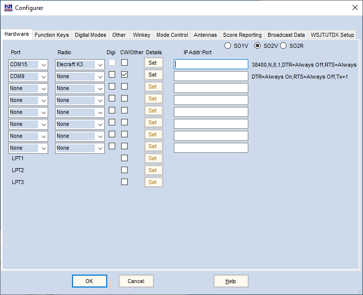
The Hardware tab is used to set up your radios, packet interfaces, telnet connections, CW/PTT/digital ports and the interfaces to other devices, such as SO2R controllers, multi-purpose interfaces, and keyers, if they require serial or parallel ports. Set the values appropriate to your station. If you do not have one of the items listed connected to a port, make sure the port selection is ‘None’ and the check boxes are not checked for that port.
Hardware setup options
The program supports up to 8 serial ports, each of which can be anywhere in the range COM1-COM99, and 3 parallel ports (LPT1 – LPT3).
Set up each port depending on what equipment is connected and enter the appropriate information.
A more detailed explanation of each of the controls on this window follows.
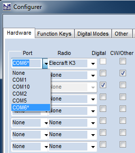
- Port – for each device that is to be connected via a COM port, the COM port number is selected in this column from a pull-down list:
This example screen shot shows a case in which three COM ports are being used. COM6 is used for radio control of an Elecraft K3. COM2 is being used for a Winkeyer for CW keying. COM10 is connected to a TNC or terminal unit for RTTY. The radio has two receivers and the program is configured for SO2V (Single Operator, 2 VFOs) with two Entry windows, one for each VFO/receiver.
- This list displays all of the COM ports the program was able to open. In this example, COM1, COM2, COM5 and COM10 were found by the program when the Configurer window was opened. These ports might include real serial ports, USB-to-serial adapters, and/or virtual serial ports created by software drivers (e.g. microHam Router, LP-Bridge, etc.)
- COM6 also appears on the example list above, but with an asterisk beside it. The asterisk indicates that this port was previously configured at this position in the N1MM Logger.ini file, but when the Configurer was opened, the program was unable to open the port. This could be the result of a USB-to-serial adapter being unplugged, or as the result of other software that had previously created a virtual serial port but that was not running at the time the Configurer was opened
- If this asterisked device is left configured for COM6, after exiting the Configurer the program will issue a warning that it was unable to open the port. The function that should be provided by this port will be unavailable. This can be corrected by connecting the USB adapter or creating the software virtual port in the other software, then reopening and closing the Configurer
- If a different COM port is selected from the list, the missing COM port denoted by the asterisk will disappear from the pull-down list
- One of the options in the list of ports is TCP. This is used for radios that support radio control via TCP (Ethernet) – to use this you will need an Ethernet cable from the radio’s LAN port to your router (or an Ethernet switch or Wifi access point that connects to your LAN). If TCP is selected, enter the IP address and TCP port used by the radio in the box in the IP Addr:Port column. Consult your radio’s documentation to find out how to determine the IP address and port number
- Radio – The pull-down list in the box in this column can be used to select a radio that is to be interfaced with the program using this port for radio control, i.e. control of the radio’s frequency and mode. A maximum of two radios can be connected. Select ‘None’ if this port is not being used for radio control. If you have only one radio connected, only one of the boxes in this column should be configured to anything other than “None”
- Digital – Checking this box means this port is used for digital communication (MMTTY/MMVARI/Fldigi engine or TNC). This box cannot be checked if this port is used for radio control. Conversely, if this box is checked the pull-down list in the Radio column is disabled. Not all ports used for digital communication are configured here; check this box only if one of the following conditions is met:
- Use this to indicate a port that is used for a TU or TNC for RTTY
- Use it to indicate a port that is used for PTT from MMVARI in digital modes. This is not necessary with the external digital engines (MMTTY, 2Tone and Fldigi), only with MMVARI
- Use it to indicate a port that will be time-shared between digital and non-digital modes. This could be, for example, a port that is used for serial port CW keying when the operating mode is CW, and for FSK and/or PTT keying when the operating mode is RTTY. The CW/Other box will also be checked for such a time-shared port
- If the only time the port is used is in digital modes from MMTTY, 2Tone or Fldigi, it is not necessary to check this check box; simply configure the port directly within the digital engine without setting it up in the Configurer
- If you control PTT from the radio control port or from a Winkeyer, do not check the Digital box for that port
- If you are using a port for FSK keying with MMTTY or MMVARI via the EXTFSK or EXTFSK64 add-in, the port cannot be time-shared, and therefore you would not check the Digital box for this port
- CW/Other – Check this box if this port is used for hardware-keyed CW or PTT, a Winkeyer, a footswitch, a DVK or an SO2R controller. You do not need to check this box to enable PTT via radio control commands; this is done using a check box in the port setup dialog instead. The CW/Other selection may be made in combination with a Radio or Digital selection provided the uses are compatible (e.g. keying CW on the DTR control line can be compatible with radio control on the same port if your hardware interface supports it). In addition to the serial ports, the CW/Other box can also be selected for one or more parallel ports (LPT1/2/3) to be used for CW or PTT keying or for other types of device control
To configure a port for a Winkeyer, first select the port used by the Winkeyer in the left-most column of the Hardware tab. Then check the CW/Other box in that same row. finally, click the Set button and check the Winkeyer box in the dialog that appears. Apart from possibly the Radio Nr box, you do not need to change anything else in this dialog; the defaults are designed to work with a Winkeyer.
Note that having multiple ports configured for CW or PTT can cause problems; for example, having two methods of PTT control operating at the same time can result in the radio failing to switch to transmit, or worse, locking up in transmit at the end of a function key message. This is particularly a problem with some radios when one of the methods is PTT via radio command and the other method is a hardware keying method. Pick one method of CW keying and one method of PTT control, check the CW/Other box for the port or ports you need for them and complete the port configuration using the Set button, and make sure CW/Other is not checked for ports that you are not currently using. Note that the PTT output from a Winkeyer is active in SSB and RTTY as well as in CW, i.e. if you are using this output from the Winkeyer, you do not need a separate method for PTT for SSB or RTTY. For digital modes, do not configure PTT control from the digital engine (MMTTY or Fldigi) if you have PTT control operating from the main N1MM Logger program.
- Details – Click on the Set button in this column to open a window with a set of controls that depends on what is selected in the preceding columns (Radio, Digital, Packet, CW/Other). To the right of the details column is a summary of the detailed settings. See below for details.
- IP Addr:Port – This is only used for radios using TCP instead of a serial port for radio control, or being controlled via a TCP-to-serial adapter. Enter TCP for the port number in the Port column, and enter the radio’s IP address and TCP port number in the box in the IP Addr:Port column.
The radio buttons in the upper right are used to fit the program to your desired mode of operation.
- SO1V – Single Operator 1 VFO
- This mode is used with a single Entry window, and is the normal operating mode for a single-receiver radio. In SO1V mode, the backslash, Pause, Ctrl+Right-arrow, grave accent(`) and Ctrl+Alt+K keys are disabled to prevent opening the second Entry window. If the second Entry window and/or Bandmap window were open when the Configurer was opened, they will be closed when exiting the Configurer after selecting SO1V
- SO2V – Single Operator 2 VFO (one radio, using both VFOs)
- Permits using two separate Entry windows, one for each VFO; the full SO2V functionality is usable only with radios that have dual receivers
- SO2R – Single Operator 2 Radios
- Permits using two separate Entry windows, one for each radio
Set Button Examples
Some examples of the dialog box that appears when you click on the Set button are given here.
Radio Control Port
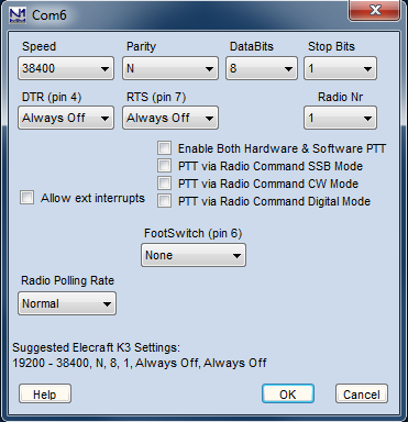
For a port selected for radio control:
- Speed – The speed of the serial port (check the manual of your radio)
- Parity – The parity used (check the manual of your radio)
- Data Bits – The number of data bits used (check the manual of your radio)
- Stop Bits – The number of stop bits used (check the manual of your radio)
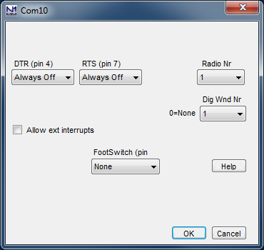
- DTR – The following selections can be made for DTR (pin 4 on DB9 connector):
- PTT – used for keying the radio
- CW – used for sending CW to the radio
- Note: The PTT and CW selections require either a keying circuit between DTR and the radio’s PTT input or CW key jack, or a transceiver that can accept direct switching on the DTR line on its radio control port (such as an Elecraft K3). The CW/Other check box for this port in the main Configurer window must be checked to enable PTT or CW switching via DTR
- Always on – DTR is always ‘high’
- Always off – DTR is always ‘low’
- Handshake – DTR is used for handshaking
- RTS – The same selections as for DTR can be made for RTS (pin 7 on DB9 connector):
- PTT – used for keying the radio
- CW – used for sending CW to the radio
- Note: The PTT and CW selections require either a keying circuit between RTS and the radio’s PTT input or CW key jack, or a transceiver that can accept direct switching on the RTS line on its radio control port (such as an Elecraft K3). The CW/Other check box for this port in the main Configurer window must be checked to enable PTT or CW switching via RTS
- Always on – RTS is always ‘high’
- Always off – RTS is always ‘low’
- Handshake – RTS is used for handshaking
- When both RTS and DTR are set to PTT they will both be keyed for PTT with the set PTT delay
- When using a self-powered interface for radio control, set DTR and/or RTS to Always On to supply power to the interface
- Icom Addr (hex) – The hex address for the radio. Enter without the “H” i.e. 26 not 26H. This field is only shown when an Icom is the selected radio
- Radio Nr – The radio controlled from this port:
- In SO1V (one radio, one VFO used) Radio Nr = 1
- In SO2V (one radio, two VFOs) Radio Nr = 1
- In SO2R select the radio (1 or 2) that will be controlled from this port
- PTT Delay (msec) – This box only appears if DTR or RTS is set to PTT. It is used to configure a delay between the time the PTT signal is switched and CW sending starts, in order to prevent hot-switching
- Enable Both Hardware & Software PTT – This check box allows both hardware and software PTT control methods to be used. USE WITH CAUTION. With some radios, using software and hardware PTT control at the same time can lead to problems such as the radio hanging up in transmit at the end of CW or RTTY messages
- Allow ext. interrupts – Allow external interrupts from this port (DSR – pin 6), e.g. from a footswitch. An interrupt on this line will bring focus to the Entry window and stop a CQ in progress. See FootSwitch settings below
- PTT via Radio Command Digital Mode – If this check box is checked, a software radio command will be used to control PTT in digital modes
- PTT via Radio Command SSB Mode – If this check box is checked, a software radio command will be used to control PTT in SSB modes
- PTT via Radio Command CW Mode – If this check box is checked, a software radio command will be used to control PTT in CW mode
- By using these check boxes selectively, you can choose to control PTT in some modes and not others (e.g. controlling PTT in digital modes for FSK RTTY while using VOX for SSB and QSK for CW)
- FootSwitch – It is possible to connect a separate footswitch to each serial or parallel port. A pull-up resistor is needed (see the Interfacing section of the manual for detailed instructions). Multiple footswitches (one per serial or parallel port) can be used with different settings for each footswitch.
If the interface allows it to be broken out separately, the DSR input (pin 6 on a 9-pin serial port) can be used for one of the following options. The external interrupts box on the radio control port should NOT be checked for most applications. It causes additional code to be executed that may affect the radio control operation. For all footswitch options except “First One Wins”, the DSR input should be low (0V or negative) when the footswitch is not pressed and pulled high (greater than 3V) when the footswitch is pressed. The footswitch operates on the “active” radio. The RadioNr box selection is not used (ignored) for the footswitch.- None – No footswitch on this serial port
- ESM Enter – Pressing Footswitch (DSR input transitions from a low to a high) will cause the same action as pressing Enter key in ESM mode
- Typing Focus – Pressing Footswitch (DSR input transitions from a low to a high) will switch typing focus
- Switch Radios – Pressing Footswitch (DSR input transitions from a low to a high) will switch the radios (in SO2R)
- Normal – Pressing the footswitch (DSR input transitions from a low to a high) will behave if it was connected to the PTT of the active radio transmitter (radio with TX focus or red dot).
- F1 – Pressing Footswitch (DSR input transitions from a low to a high) will cause the same action as pressing function key F1
- F2 – Pressing Footswitch (DSR input transitions from a low to a high) will cause the same action as pressing function key F2
- F3 – Pressing Footswitch (DSR input transitions from a low to a high) will cause the same action as pressing function key F3
- F4 – Pressing Footswitch (DSR input transitions from a low to a high) will cause the same action as pressing function key F4
- F11 – Pressing Footswitch (DSR input transitions from a low to a high) will cause the same action as pressing function key F11
- F12 – Pressing Footswitch (DSR input transitions from a low to a high) will cause the same action as pressing function key F12
- Band lockout – Implemented mostly for multi user stations to block a second signal on the same band/mode. It may be useful for single users as well. This mode should allow you to control PTT for both radios (in case of SO2R) in different modes (SSB/CW). The advantage of using it (compared to a foot switch directly connected to the radio) is that it stops AutoCQ and Dueling CQ’s. Multiple footswitches are supported but a Band Lockout and a First One Wins footswitch can not be used on the same computer.
- First One Wins – This selection is intended for multi stations that want to prevent other transmitters from beginning a transmission. The computer needs to have network mode enabled. The DSR input is active when low (0V or negative) and intended to be connected to an open collector PTT line of the partner station. Before the station begins a transmission, the state of the DSR input is checked. If low (meaning that the partner station is transmitting), the station will not transmit. Note that the DSR sense is the reverse of the footswitch options above. Pull DSR high (greater than 3V) with a resistor and connect the DSR input to the active low open-collector PTT of the partner station. If more than one station needs to be interlocked, add a GE diode in series with the open collector PTT line creating a wire-OR circuit. Multiple footswitches are supported but a Band Lockout and a First One Wins footswitch can not be used on the same computer.
- Esc – This selection executes the Esc key press code when the DSR input transitions from a low to a high.
- Radio Polling Rate – use this to change the rate at which the radio is polled – Normal, 50% Slower or 100% Slower. The 50% Slower setting increases the time between polls to 1.5 times normal, and the 100% Slower setting increases the time between polls to 2 times normal.
- Help – used to display Help for the Configurer from the on-line manual
- OK – save the settings and exit this dialog window
- Cancel – exit this window without saving the settings
CW/Other Serial Port
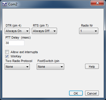
For a port whose CW/Other check box is checked:
- DTR – The following selections can be made for DTR (pin 4 on DB9 connector):
- PTT – used for keying the radio
- CW – used for sending CW to the radio
- Note: The PTT and CW selections require a keying circuit between DTR and the radio’s PTT input or CW key jack. The CW/Other check box for this port in the main Configurer window must be checked to enable PTT or CW switching via DTR
- Always on – DTR is always ‘high’
- Always off – DTR is always ‘low’
- Handshake – DTR is used for handshaking
- RTS – The same selections as for DTR can be made for RTS (pin 7 on DB9 connector):
- PTT – used for keying the radio
- CW – used for sending CW to the radio
- Note: The PTT and CW selections require a keying circuit between RTS and the radio’s PTT input or CW key jack. The CW/Other check box for this port in the main Configurer window must be checked to enable PTT or CW switching via RTS
- Always on – RTS is always ‘high’
- Always off – RTS is always ‘low’
- Handshake – RTS is used for handshaking
- Radio Nr – The radio that this port is used with:
- In SO1V (one radio, one VFO used) Radio Nr = 1
- In SO2V (one radio, two VFOs) Radio Nr = 1
- In SO2R select the radio (1 or 2) that this port is used with
- PTT Delay (msec) – This box is used to configure a delay between the time the PTT signal is switched and CW sending starts, in order to prevent hot-switching an amplifier, for example
- Allow ext. interrupts – Allow external interrupts from this port (DSR – pin 6), e.g. from a footswitch. An interrupt on this line will bring focus to the Entry window and stop a CQ in progress
- Winkey – Select when using a Winkeyer. Speed, Parity, Data bits, Stop bits or Handshake settings do not have to be adjusted; they are fixed and set by the program. Settings for the keyer are made on the Winkeyer tab in the Configurer. If you select Winkeyer, DO NOT set DTR to CW.
- Note: Only one Winkeyer is supported, but a single Winkeyer can key two radios
- Two Radio Protocol – Support for an SO2R controller using a COM port. This provides USB-only SO2R control (no LPT port required). Protocol used may be either the microHam proprietary protocol (MK2R) or OTRSP (Open Two Radio Switching Protocol)
- More info in the chapter on supported hardware
- FootSwitch – It is possible to connect a separate footswitch to each serial or parallel port. A pull-up resistor is needed (see the Interfacing section of the manual for instructions). Multiple footswitches (one per serial or parallel port) can be used with different settings for each footswitch.
Pin 6 on the serial port can be used for one of the following options (if external interrupts are enabled on this port). The footswitch operates on the “active” radio. The RadioNr box selection is not used (ignored) for the footswitch.- None – No footswitch on this serial port
- ESM Enter – Pressing Footswitch will cause the same action as pressing Enter key in ESM mode
- Typing Focus – Pressing Footswitch will switch typing focus
- Switch Radios – Pressing Footswitch will switch the radios (in SO2R)
- Normal – Pressing the footswitch will behave if it was connected to the PTT of the active transmitter and is automatically connected to the proper (active) radio.When the footswitch is released the focus will be set to main Entry window
- F1 – Pressing Footswitch will cause the same action as pressing function key F1
- F2 – Pressing Footswitch will cause the same action as pressing function key F2
- F3 – Pressing Footswitch will cause the same action as pressing function key F3
- F4 – Pressing Footswitch will cause the same action as pressing function key F4
- F11 – Pressing Footswitch will cause the same action as pressing function key F11
- F12 – Pressing Footswitch will cause the same action as pressing function key F12
- Band lockout – Implemented mostly for multi user stations to block a second signal on the same band/mode. It may be useful for single users as well. This mode should allow you to control PTT for both radios (in case of SO2R) in different modes (SSB/CW). The advantage of using it (compared to a foot switch directly connected to the radio) is that it stops AutoCQ and Dueling CQ’s. Multiple footswitches are supported but a Band Lockout and a First One Wins footswitch can not be used on the same computer
- First One Wins – This mode is intended for multi stations that want to prevent other transmitters from beginning a transmission. The COM port DSR input is active when low (0V or negative) and intended to be connected to an open collector PTT line of the partner station. Note that the DSR sense is the reverse of the footswitch options above. Pull DSR high (greater than 3V) with a resistor and connect the DSR input to the active low open-collector PTT of the partner station. If more than one station needs to be interlocked, add a diode in series with the open collector PTT line creating a wire-OR circuit. Before the station begins a transmission, the state of the DSR input is checked. If low (the partner station is transmitting), the current station will not transmit. Multiple footswitches are supported but a Band Lockout and a First One Wins footswitch can not be used on the same computer.
- Help – used to display Help for the Configurer from the on-line manual
- OK – save the settings and exit this dialog window
- Cancel – exit this window without saving the settings
Digital Serial Port
For a COM port for which the Digital check box has been checked, either in order to use a TNC or to time-share the port:
- DTR – The following selections can be made for DTR (pin 4 on DB9 connector); if the port is time-shared, these selections will only apply in non-digital modes:
- PTT – used for keying the radio
- CW – used for sending CW to the radio
- Note: The PTT and CW selections require a keying circuit between DTR and the radio’s PTT input or CW key jack. The CW/Other check box for this port in the main Configurer window must be checked to enable PTT or CW switching via DTR
- Always on – DTR is always ‘high’
- Always off – DTR is always ‘low’
- Handshake – DTR is used for handshaking
- RTS – The same selections as for DTR can be made for RTS (pin 7 on DB9 connector); if the port is time-shared, these selections will only apply in non-digital modes
- PTT – used for keying the radio
- CW – used for sending CW to the radio
- Note: The PTT and CW selections require a keying circuit between RTS and the radio’s PTT input or CW key jack. The CW/Other check box for this port in the main Configurer window must be checked to enable PTT or CW switching via RTS
- Always on – RTS is always ‘high’
- Always off – RTS is always ‘low’
- Handshake – RTS is used for handshaking
- Radio Nr – The radio this port is used with:
- In SO1V (one radio, one VFO used) Radio Nr = 1
- In SO2V (one radio, two VFOs) Radio Nr = 1
- In SO2R select the radio (1 or 2) that this port is used with
- Dig Wnd Nr – This MUST be set to indicate which Digital Interface window uses this port. If it is set to 0, the port will not be used in digital modes
- If only one DI window is used (e.g. SO1V), select 1
- If two DI windows are used, select the DI window number this port will be used for
- Allow ext. interrupts – Allow external interrupts from this port (DSR – pin 6), e.g. from a footswitch. An interrupt on this line will bring focus to the Entry window and stop a CQ in progress; non-digital modes only
- FootSwitch – It is possible to connect a separate footswitch to each serial or parallel port. A pull-up resistor is needed (see the Interfacing section of the manual for instructions). Multiple footswitches (one per serial or parallel port) can be used with different settings for each one.
Pin 6 on the serial port can be used for one of the following options (if the interface allows this line to be broken out and external interrupts are enabled on this port). The footswitch operates on the “active” radio. The RadioNr box selection is not used (ignored) for the footswitch.- None – No footswitch
- ESM Enter – Pressing Footswitch will cause the same action as pressing Enter key in ESM mode
- Typing Focus – Pressing Footswitch will switch typing focus
- Switch Radios – Pressing Footswitch will switch the radios (in SO2R)
- Normal – Pressing the footswitch will behave if it was connected to the PTT of the active transmitter and is automatically connected to the proper (active) radio. When the footswitch is released the focus will be set to main Entry window
- F1 – Pressing Footswitch will cause the same action as pressing function key F1
- F2 – Pressing Footswitch will cause the same action as pressing function key F2
- F3 – Pressing Footswitch will cause the same action as pressing function key F3
- F4 – Pressing Footswitch will cause the same action as pressing function key F4
- F11 – Pressing Footswitch will cause the same action as pressing function key F11
- F12 – Pressing Footswitch will cause the same action as pressing function key F12
- Band lockout – Implemented mostly for multi user stations to block a second signal on the same band/mode. It may be useful for single users as well. This mode should allow you to control PTT for both radios (in case of SO2R) in different modes (SSB/CW). The advantage of using it (compared to a footswitch directly connected to the radio) is that it stops AutoCQ and Dueling CQ’s. Multiple footswitches are supported but a Band Lockout and a First One Wins footswitch can not be used on the same computer
- First One Wins – This mode is intended for multi stations that want to prevent other transmitters from beginning a transmission. The COM port DSR input is active when low (0V or negative) and intended to be connected to an open collector PTT line of the partner station. Note that the DSR sense is the reverse of the footswitch options above. Pull DSR high (greater than 3V) with a resistor and connect the DSR input to the active low open-collector PTT of the partner station. If more than one station needs to be interlocked, add a diode in series with the open collector PTT line creating a wire-OR circuit. Before the station begins a transmission, the state of the DRS input is checked. If low (the partner station is transmitting), the current station will not transmit. Multiple footswitches are supported but a Band Lockout and a First One Wins footswitch can not be used on the same computer.
- Help – used to display Help for the Configurer from the on-line manual
- OK – save the settings and exit this dialog window
- Cancel – exit this window without saving the settings
Parallel (LPT) Port
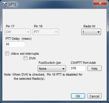
For an LPT port:
- Pin 17 – always used for CW keying; greyed out because it cannot be changed
- Pin 16 – used for PTT, except when an external DVK is used; greyed out because it cannot be changed
- Radio Nr – The radio that this port is used with:
- In SO1V (one radio, one VFO used) Radio Nr = 1
- In SO2V (one radio, two VFOs) Radio Nr = 1
- In SO2R without an automatically controlled SO2R box, select the radio (1 or 2) that this port is used with
- If using an LPT SO2R box, set the Radio Nr for the first LPT port to Both. Pin 14 will be used to select the radio for CW, PTT, etc.
- If using band data lines with this setup, band data for the first radio is routed to the first LPT port (Radio Nr = Both) and band data for the second radio is routed to the second LPT port (Radio Nr = 2)
SO2R and LPT CW, the LOWEST numbered port must have the CW output set to BOTH if it is used with a conventional LPT SO2R box (DXD, KK1L, N6BV, etc.) or microHAM MK2R/MK2R+ in LPT (Classic auto control) mode, The LPT with CW, PTT and the TX/RX/Split controls must be connected to the SO2R controller. If N1MM is configured for CW on TWO LPT ports (first port: Radio=1, second port Radio=2) then CW will be present only on the port representing the radio with transmit focus.
- PTT Delay (msec) – This box is used to configure a delay between the time the PTT signal is switched and CW sending starts, in order to prevent hot-switching an amplifier, for example
- Allow ext. interrupts – Allow external interrupts from pin 15, e.g. from a footswitch. An interrupt on this line will bring focus to the Entry window and stop a CQ in progress
- DVK – DVK interface for MK2R, W9XT & other external DVKs. See this page for detailed information, pinouts, and limitations
- When DVK is selected, Antenna selection via the LPT port is disabled (the DVK pins and the antenna pins on the LPT port overlap)
- When using an external DVK, all of the Run and S&P SSB function keys should be set to empty.wav and not left blank
- microHAM MK2R: if DVK is checked, N1MM Logger will use the DVK in Router instead of its own DVK support
- FootSwitch – It is possible to connect a separate footswitch to each serial or parallel port. A pull-up resistor is needed between the footswitch input (pin 15 on the parallel port) and +5 VDC (see the Interfacing section of the manual for instructions). Multiple footswitches (one per port) can be used with different settings for each one.
Pin 15 on the parallel port can be used for one of the following options. The footswitch operates on the “active” radio. The RadioNr box selection is not used (ignored) for the footswitch.- None – No footswitch
- ESM Enter – Pressing Footswitch will cause the same action as pressing Enter key in ESM mode
- Typing Focus – Pressing Footswitch will switch typing focus
- Switch Radios – Pressing Footswitch will switch the radios (in SO2R)
- Normal – Pressing the footswitch will behave if it was connected to the PTT of the active transmitter and is automatically connected to the proper (active) radio.When the footswitch is released the focus will be set to main Entry window
- F1 – Pressing Footswitch will cause the same action as pressing function key F1
- F2 – Pressing Footswitch will cause the same action as pressing function key F2
- F3 – Pressing Footswitch will cause the same action as pressing function key F3
- F4 – Pressing Footswitch will cause the same action as pressing function key F4
- F11 – Pressing Footswitch will cause the same action as pressing function key F11
- F12 – Pressing Footswitch will cause the same action as pressing function key F12
- Band lockout – Implemented mostly for multi user stations to block a second signal on the same band/mode. It may be useful for single users as well. This mode should allow you to control PTT for both radios (in case of SO2R) in different modes (SSB/CW). The advantage of using it (compared to a footswitch directly connected to the radio) is that it stops AutoCQ and Dueling CQ’s. Multiple footswitches are supported but a Band Lockout and a First One Wins footswitch can not be used on the same computer
- First One Wins – This mode is intended for multi stations that want to prevent other transmitters from beginning a transmission. The input is active when low (0V or negative) and intended to be connected to an open collector PTT line of the partner station. Note that the sense is the reverse of the footswitch options above. Pull pin 15 high (greater than 3V) with a resistor and connect the input to the active low open-collector PTT of the partner station. If more than one station needs to be interlocked, add a diode in series with the open collector PTT line creating a wire-OR circuit. Before the station begins a transmission, the state of the input is checked. If low (the partner station is transmitting), the current station will not transmit. Multiple footswitches are supported but a Band Lockout and a First One Wins footswitch can not be used on the same computer.
- CW/PTT Port Addr – specify port address (Required!)
- The initial default address in this box, if there is one, may not be correct in some computers or for some add-in cards; if the port does not work, check the port’s properties in Device Manager to determine the correct address. There is more information on this topic in the Interfacing chapter
- Help – used to display Help for the Configurer from the on-line manual
- OK – save the settings and exit this dialog window
- Cancel – exit this window without saving the settings
Additional signals are also present on the parallel port. See the Interfacing chapter for more detailed info.
PTT Options
Originally, Push-to-Talk (PTT) was actually a copyrighted term, describing how operators of one company’s radios could press a button on their microphones to switch from Receive to Transmit. Over the years, however, it has come to denote any form of transmit/receive switching external to the radio. It could be as simple as a microphone button or a footswitch working directly with the radio, or as sophisticated as control by a logging program.
N1MM Logger+ provides several options. As described above, you should pick only one of these options:
- PTT via serial or parallel port – This option uses the RTS or DTR lines on a serial port or pin 16 on an LPT port. This more-or-less standard method usually requires a simple one-transistor interface to switch the radio. USB-to-serial adapters can be used for this function; ordinary USB-to parallel (printer) adapters will not work, because they lack the ability to control individual lines in the parallel interface – the one exception is the SO2RXLAT interface developed by PIEXX.
- PTT via Winkeyer – If a Winkeyer, a keyer that emulates the Winkeyer, or an interface incorporating a Winkeyer chip is used, its PTT output can be used in all modes to control transmit/receive switching.
- PTT via radio command – For radios that support it, this option eliminates any need for external hardware other than a serial port cable or a serial to USB converter. Check your radio manual for details.
Warning: At the moment, there is no provision for both controlling radio PTT via radio command and simultaneously introducing a delay before the Logger begins to send a stored message, so if you need to protect external equipment (see below) you should not use this option.
PTT Delay
This is an important aspect of PTT operation. Some amplifiers are slower than many radios, so if the radio begins to transmit as soon as PTT is asserted, it may result in hot-switching of the amplifier’s internal transmit/receive relays, which can result in damage. In addition, for VHF operation, preamplifiers located at the antenna may need to be properly sequenced to avoid damage from transmitted RF.
- In the case of PTT via serial or parallel port, this delay is set in the Configurer, on the Hardware tab, when configuring a port for PTT. Note that for a serial port, you will only see this option if you have first selected PTT on either RTS or DTR.
- For Winkeyer PTT, set this delay (called lead-time in Winkeyer parlance) on the Winkeyer tab of the Configurer. This affects both hand-sent CW and stored messages. You will probably find that any value over 20 milliseconds (probably enough for most amps) throws off your hand-sent keying.
Other Information
Under 32 and 64 bit bit Windows operating systems, using the parallel and serial ports for PTT and CW keying requires a special dll called inpout32.dll. This dll is installed with the Logger, but if the file is not installed for some reason, information on finding and installing it can be found in the Installation chapter.
Function Keys Tab
Function key operation is controlled from this tab.
Function Keys Field Descriptions
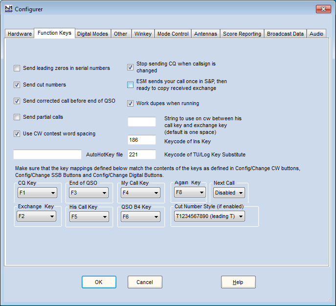
- Send leading zeros in serial numbers – Serial numbers, which are sent either using the # macro or the {EXCH} macro (if the Sent Exchange box in the Contest Setup contains 001), may be sent either with or without leading zeros (e.g. 003 or just 3), depending on whether this option is checked or not. In CW, the “cut numbers” option can be used to send the leading zeros as T or O instead of 0. The leading zeros option does not affect numbers other than serial numbers
- Send cut numbers – In CW this causes serial numbers to be sent using the Cut Number Style set at the bottom of the dialog. Ctrl+G can be used to toggle this option while operating. The new status after toggling will be shown in the status line at the bottom of the entry window. Numbers other than serial numbers will not be affected by this option. The cut numbers option does not apply to SSB or digital modes
- Send corrected call before end of QSO – If the callsign in the callsign box is changed (corrected) after answering a call and sending your exchange but before the contact has been logged, then the corrected callsign (from the callsign box) will be sent by the End of QSO Key (or any other action that triggers it, such as the ‘ key, or the Enter key in ESM) before the End of QSO message, e.g. ‘PA1M TU DE N1MM’ instead of ‘TU DE N1MM’. If F3 is not pressed until after the contact has already been logged, the corrected callsign will not be sent. In phone modes, if the F3 key invokes a wav file then the program will use letter/number wav files to send the callsign first.
- Send partial calls – CW only. When sending a corrected call using the previous option, only the corrected part will be sent (prefix or suffix). If not checked the whole call will be sent.
- AutoHotKey file – Type here the name of any AutoHotKey script(.ahk) file that you wish to have started and stopped when N1MM Logger+ is started and stopped. To use this feature, AutoHotKey must be installed on your computer. Download it at this page.
- AutoHotKey scripts are very useful for keyboard remapping. Examples can be found in the Third Party Software section of the manual. If you put this file in the Support Files sub-folder of your N1MM Logger+ user files folder, then you need only name the file itself; alternatively you can use the entire path to a script file anywhere on your computer.
- Use CW contest word spacing – This setting changes the spacing between words in your CW, where “N1MM 599 5” is 3 words. Default is 6 bits for “contest spacing”. When box is not checked, 7 bits between words is used, which is “normal spacing”
- Stop sending CQ when callsign is changed – Typing a character in the callsign field will stop a (repeated) CQ
- ESM sends your call once in S&P, then ready to copy received exchange – This is often called the “Big Gun / Little Pistol switch” . When selected and in Enter Sends Message mode the cursor moves to the Exchange field when there is something in the Callsign field and Enter is pressed (so it does not keep the cursor in the callsign field). If you don’t usually get a station on the first call then deselect this option. Read more about Big Gun \ Little Pistol operation under((ESM+-+Enter+Sends+Message|ESM)).
- Work dupes when running – This determines what is sent when a dupe calls you and you press Enter in ESM. Normally you DO want to work dupes, so this box would normally be checked. See the chapter Off topic for a discussion
- String to use on cw between his call key and exchange key (default is one space) – Just as it says. Example ‘ ur ‘
- Keycode of Ins Key Substitute – Enter the number for the Ins Key substitute (to send the other station’s callsign plus your exchange) as mapped below in this configurer dialog. Defaults to 186, the ; character. The program can automatically enter the keycode in this field . Place the cursor in the keycode field and press the key you want to substitute, it will put the correct keycode in. 186 is an extended key code. Not all keyboards map keys the same way. Note that you can’t use a Shift, Ctrl, Alt etc. key. I would not advise using a key like Numeric + that is already in use. It may or may not work. In this case Numeric +, does NOT work
- Keycode of TU/Log Key Substitute – Enter the number for the TU/Log Key substitute (to combine sending the TU key and logging the contact) as mapped below in this configurer dialog. Defaults to 222, the ‘ character. The program can automatically enter the keycode in this field . Place the cursor in the keycode field and press the key you want to substitute, it will put the correct keycode in. 222 is an extended key code. Not all keyboards map keys the same way. Note that you can’t use a Shift, Ctrl, Alt etc. key. I would not advise using a key like Numeric + that is already in use. It may or may not work. This particular case (Numeric +) does NOT work
- Cut Number Style – the following cut number styles can be chosen:
- T1234567890 (leading T) – leading 0 will be replaced with a T. So 007 will become TT7 and 030 will become T30
- O1234567890 (leading O) – leading 0 will be replaced with an O. So 007 will become OO7 and 030 will become O30
- T123456789T (all T) – all zeros will be replaced with a T. So 007 will become TT7 and 030 will become T3T
- O123456789O (all O) – all zeros will be replaced with an O. So 007 will become OO7 and 030 will become O3O
- T12345678NT (TN) – all zeros will be replaced with a T, all nines with an N. So 097 will become TN7 and 090 will become TNT
- O12345678NO (ON) – all zeros will be replaced with an O, all nines with an N. So 097 will become ON7 and 090 will become ONO
- TA2345678NT (TAN) – all zeros will be replaced with a T, all nines with an N, all ones with an A. So 091 will become TNA and 190 will become ANT
- TA234E678NT (TAEN) – all zeros will be replaced with a T, all nines with an N, all ones with an A, all fives with an E. So 091 will become TNA and 1590 will become AENT
- TAU34E67DNT – the zero, one, two, five, eight, nine will be replaced with a T, A, U, E, D, N respectively
Remapping Function Keys
Select which function keys to send messages. Each type of message has a combo box for you to set the appropriate function key. If the program is sending the wrong message check here first. The only restriction is that a key must mean the same thing in Running and in S&P. Function keys do not have to be unique for a selected message. There is little reason to do so although if you want it can be done. For the following messages a function key can be selected
- CQ Key – defaults to F1
- Exchange Key – defaults to F2
- End of QSO Key – defaults to F3
- His Call Key – defaults to F5
- My Call Key – defaults to F4
- QSO B4 Key – defaults to F6 (can be disabled)
- Again Key – defaults to F8 (can be disabled)
- Next Call Key – defaults to Disabled
| ESM mode | Work dupes when running | Mode | QSO B4 key | Again key | Action | Result action |
| On | don’t work dupes | Run | Disabled | F-key | DUPE callsign entered | Send AGN message when Enter pressed |
| On | don’t work dupes | Run | Disabled | Disabled | DUPE callsign entered | Send the EXCH when Enter is pressed, station will be worked and logged with Enter, Enter |
| On | don’t work dupes | S&P | Disabled | F-key | DUPE callsign entered | Pressing Enter does nothing, no blue buttons in the Entry window |
| On | don’t work dupes | S&P | Disabled | Disabled | DUPE callsign entered | Pressing Enter does nothing, no blue buttons in the Entry window |
| On | work dupes | Run | – | Disabled | DUPE callsign entered. Mistake with received QSO data | Send EXCH when Enter is pressed |
| On | don’t work dupes | Run | – | Disabled | Mistake with received QSO data | Send EXCH when Enter is pressed |
| On | – | S&P | – | Disabled | Mistake with received QSO data | Send EXCH when Enter is pressed. After the user corrects the entry, it will log and not send anything |
Digital Modes Tab
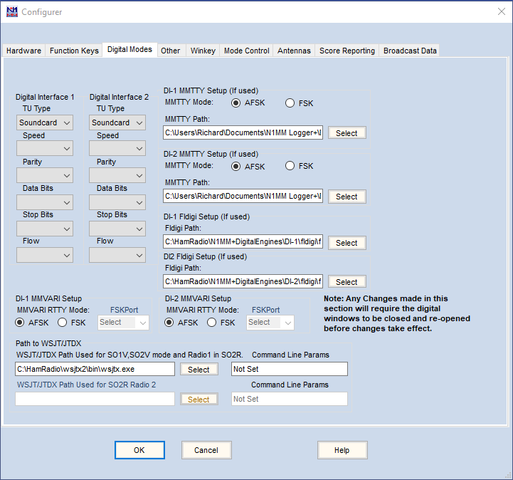
The Digital modes tab is used to set up the interfacing to external Controllers (TNCs), or to digital engines (MMTTY/MMVARI/Fldigi/2Tone) for sound card digital modes.
In SO1V mode, there is only one Digital Interface window, DI-1. In SO2V and SO2R modes, there are two Digital Interface windows, DI-1 and DI-2. Each DI window is associated with one of the two Entry windows. Each DI window is opened from the Window > Digital Interface menu item in the corresponding Entry window. The Digital Modes tab in the Configurer is used to configure both Digital Interface windows.
Digital Modes Field Descriptions
- Digital Interface 1 / 2
- TU type
- None
- Soundcard – use this selection for MMTTY, 2Tone, MMVARI or Fldigi sound card software
- Other – use this selection for a TNC or TU such as a PK-232 or KAM
- Dxp38 – for the HAL DXP-38 TU
- TinyFSK – for the K0SM TinyFSK interface
- Winkey – for the K1EL Winkeyer version 3.1 or later interface
- Note: in order to enable the Winkey interface, you also need to check the Enable RTTY Mode using Winkey check box under the Winkey tab, and set the Winkey port up under the Hardware tab if you haven’t already done so for CW
- Port, Speed, Parity, Data Bits, Stop Bits, Flow Control – Used when Other, Dxp38 or TinyFSK is selected, to set the parameters for the COM port used to communicate with the TNC or TU (e.g. 9600 baud, N, 8, 1, no flow control for the DXP-38 or TinyFSK)
- TU type
- DI-1 MMTTY Mode | DI-2 MMTTY mode
- Use the MMTTY section for 2Tone as well as MMTTY
- When using MMTTY, select whether AFSK or FSK is being used
- The serial port MMTTY will use for PTT and FSK has to be set in the MMTTY Setup. More information in the MMTTY support chapter
- When using a TinyFSK for FSK transmitting, you will still need a sound card interface for receiving; even though you are actually going to transmit using FSK, you configure the sound card interface for AFSK
- DI-1 MMTTY Path | DI-2 MMTTY Path
- The path to the MMTTY (or 2Tone) engine goes here including the file name of the program
- The path and file name can be selected using the Select buttons
- The two instances of MMTTY should be in two separate folders. You must do this if you want the MMTTY settings in the two instances to be different (e.g. left vs. right channel, different sound cards, etc.)
- DI-1 Fldigi Path | DI-2 Fldigi Path
- The path to the Fldigi engine goes here including the file name of the program
- The path and file name can be selected using the Select buttons
- DI-1 MMVARI RTTY Mode | DI-2 MMVARI RTTY Mode
- When using MMVARI for RTTY, select whether AFSK or FSK is being used
- If AFSK is selected the serial port (if any) with a check in the Digital check box and with Dig Wnd Nr corresponding to the DI window number will get passed to MMVARI when the DI window is opened, so that MMVARI can use it for PTT control
- If FSK is selected, the port to be used for PTT control is not passed to MMVARI. It must be defined in the FSK8250, EXTFSK or EXTFSK64 setup window
- DI-1 MMVARI FSKPort | DI-2 MMVARI FSKPort
- WARNING: You must use the Windows “Run as administrator” option when starting N1MM+ if you want to use FSK with MMVARI. Running MMVARI in FSK without using “Run as administrator” will result in a program hangup or crash when the FSK8250/EXTFSK/EXTFSK64 plugin tries to write to its configuration file
- Choose FSK8250 if you are using a true serial port or a device that can simulate a serial port and handle 5-bit codes at 45.45 baud (this does not include most consumer-grade USB-to-serial adapters, but it does include some commercial interfaces, such as interfaces specifically designed to support FSK RTTY)
- When MMVARI is opened for FSK RTTY, a small window labelled FSK8250/16550 1.03 will open, or appear on the Windows Task bar. In this window you select the COM port number and the signal line to be used for PTT (RTS or DTR). FSK keying will be done on the TxD line. If this is a USB device that simulates a serial port, check Limiting speed in the MMTTY setup. You can use the _ box at the top right to minimize this window after completing the setup
- Choose EXTFSK if you are using a regular USB-to-serial adapter
- When MMVARI is opened for FSK RTTY, a small window labelled EXTFSK 1.05a will open, or appear on the Windows Task bar. In this window you select the COM port number and the signal lines to be used for FSK keying (normally TxD) and PTT (RTS or DTR). You can use the _ box at the top right to minimize this window after completing the setup
- On high-performance multi-core systems only, you may choose EXTFSK64 instead of EXTFSK. EXTFSK64 uses a more accurate timing mechanism than EXTFSK, but this mechanism uses significant CPU resources. EXTFSK64 is not appropriate for use on XP based systems or hardware running older dual-core Intel/AMD CPUs or Atom based CPUs. On systems that are capable of supporting it, EXTFSK64 can key FSK at speeds other than 45.45 baud, and it can also key FSK from LPT ports as well as USB-to-serial adapters. See http://www.qsl.net/ja7ude/extfsk/indexe.html for more detailed information on EXTFSK64
- When MMVARI is opened for FSK RTTY, a small window labelled EXTFSK64 will open, or appear on the Windows Task bar. In this window you select the COM or LPT port number and the signal lines to be used for FSK keying (normally TxD) and PTT (RTS or DTR). You can use the _ box at the top right to minimize this window after completing the setup
- Path to WSJT/JTDX (version 1.0.7845 and earlier only – in version 1.0.7860 and later, these options have been moved to the WSJT/JTDX Setup tab):
- The upper box contains the path to the WSJT (or JTDX) program that will be used from within N1MM+ for WSJT modes like FT4 and FT8. When the Window > Load WSJT/JTDX menu item is used in the Entry Window, the entry in this box tells the program where to find the WSJT or JTDX program. Use the Select button to change the path.
- To the right of the Select button is a box in which additional command-line parameters may be set for WSJT. In most installations, this box is not used.
- The lower box can be used for running WSJT-X from Radio 2 in SO2R.
- Detailed information on setting up and operating with WSJT-X or JTDX is found in the manual page for the WSJT Decode List window.
- The upper box contains the path to the WSJT (or JTDX) program that will be used from within N1MM+ for WSJT modes like FT4 and FT8. When the Window > Load WSJT/JTDX menu item is used in the Entry Window, the entry in this box tells the program where to find the WSJT or JTDX program. Use the Select button to change the path.
Other Tab
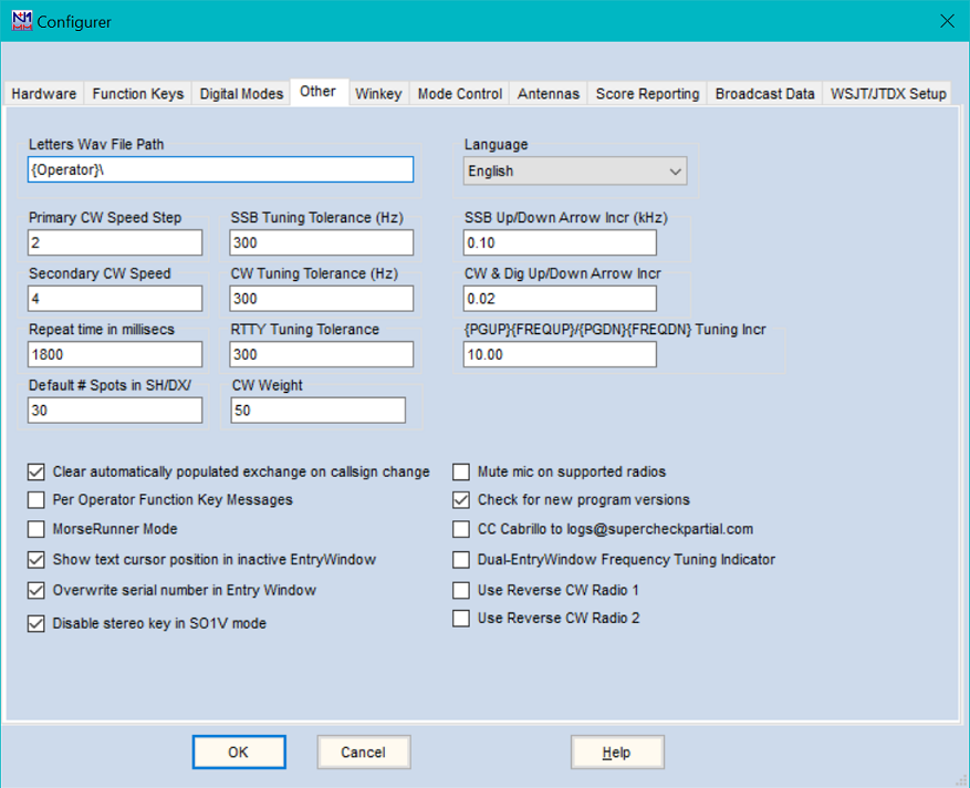
The Other tab is used to set up default values and select special modes and functions.
Other Tab Field descriptions
- DVK Letters File Path – This is where you specify the sub-path (relative to the Wav\LettersFiles subdirectory in the N1MM Logger+ User Files area) where the program will look for individual letter and number files for voicing of call signs and serial numbers in SSB. You can use {WAVDIR}\ or {OPERATOR}\ in this file path, in which case each operator (specified using OPON or Ctrl+O) will have their own separate letters file subdirectory (or possibly subdirectories, using {WAVDIR}) within the wav\LettersFiles directory
- Primary CW Speed Step – The primary speed step is used with PgUp/PgDn keys or the speed adjust buttons in the Entry Window
- Secondary CW Speed – The secondary speed step is used when Shift+PgUp/PgDn is pressed. Alt+PgUp/PgDn adjusts the CW speed of the inactive radio/VFO in SO2R/SO2V mode
- Repeat time in millisecs – Specify the CQ repeat interval in the Entry window (Auto-CQ). The default value is 1.8 seconds. Enter a value in seconds or milliseconds. The maximum value is 32767. This is the same as Ctrl+R or ‘Config | Set CQ repeat time’ in the Entry Window
- Default # Spots in – The number of spots returned by the SH/DX command in the bandmap window. The default value is 30 spots. The number of returned spots for the SH/DX command in the Telnet window is not affected by this value and has to be changed in the Telnet Options window
- SSB Tuning Tolerance (Hz) – SSB mode: Clicking on or next to a station in the bandmap window will put the call on the callsign frame (if the callsign field is empty) of the Entry window. This value gives the maximum frequency distance to the call on the bandmap when it will be put on the callsign frame. The value has to be between 0 and 20000 (20 kHz). The default value is 300
- CW Tuning Tolerance (Hz) – CW mode: Clicking on or next to a station in the bandmap window will put the call in the callsign frame (if the callsign field is empty) of the Entry window. This value gives the maximum frequency distance to the call on the bandmap when it will be put on the callsign frame. The value has to be between 0 and 20000 (20 kHz). The default value is 300
- RTTY Tuning Tolerance – RTTY mode: Clicking on or next to a station in the bandmap window will put the call on the callsign frame (if the callsign field is empty) of the Entry window. This value gives the maximum frequency distance (in Hz) to the call on the bandmap when it will be put on the callsign frame. The value has to be between 0 and 20000 (20 kHz). The default value is 300
- CW Weight – Adjusts the CW weight (between 30-70% limits). The default value is 50. This weight command works not only for serial or LPT port CW but also for Winkeyer
- SSB Up/Down Arrow Incr – This value gives the frequency jump amount (in kHz) of the up/down arrow keys, or by spinning the mouse wheel, in SSB . Set to 0.00 to disable
- NB. Never make this smaller than the smallest step your radio can make in SSB. Older Icom rigs are known to have a smallest step of 100 Hz which is quite big. When the step is made smaller than the minimum step size the Up/Down Arrows don’t seem to work. Also controls the amount of each frequency change when tuning the RIT on radios that support doing so from the computer
- CW Up/Down Arrow Incr – This value gives the frequency jump amount of the up/down arrow keys, or by spinning the mouse wheel, in CW and digital modes. Set to 0.00 to disable
- NB. Never make this smaller than the smallest step your radio can make in CW. Most rigs have a smallest step in the order of 10 Hz. When the step is made smaller than the minimum step size the Up/Down Arrows don’t seem to work. Also controls the amount of each frequency change when tuning the RIT on radios that support doing so from the computer.
- PgUp/PgDn Incr (kHz) – This value gives the frequency jump amount for the {PGUP} {PGDN} macros (Note: the PgUp and PgDn keys are not used for this; the {PGUP} and {PGDN} macros must be used in function key macros. These macro names are holdovers from early versions of N1MM Logger Classic)
- Clear automatically populated exchange on callsign change – When selected, if the callsign in the Entry window is changed by the operator, this option clears the contents of exchange fields in the Entry window that were populated (filled in) from a Call History file, from previous QSOs in the contest, or from a Telnet spot. Does not affect exchange data that have been manually filled in
- Per Operator Function Key Messages – This feature is intended for multi-operator situations where it is desirable to enable different function key messages depending on which operator has logged on the program (with Ctrl+O or the text command OPON [Callsign]).
- When the Per Operator Function Key Messages option is not checked, the function key message file specified on the Associated Files tab of the Contest Setup dialog will be used by all operators. Any operator can modify the file that is in use through the Function Key Editor.
- If a specific Associated File is not defined, then the Default message file for that mode will be used.
- When the Per Operator Function Key Messages option is checked:
- If the Station callsign is the same as the Operator callsign, the main function key message associated with the contest is selected, as above. Only the Station callsign operator can edit this function key message file; any edits performed by other operators affect only their personal copy of the message file.
- If the Station callsign and the Operator callsign are different, the current Associated Function Key Message file is copied into an operator sub-directory during the first OPON or Ctrl+O by that operator. The operator directory files are then loaded each subsequent time that operator signs on using OPON or Ctrl+O. The station callsign operator should verify that the associated function key message files are correct prior to allowing operators with different callsigns to log on, otherwise any errors in the master set will have to be corrected individually by every other operator who signs on.
- It is not necessary to create the operator directories yourself. The program code will create the necessary sub-directories and the operator directory when needed. The operator directory is a sub-directory of the directory where the base function key message files are stored (e.g. C:\Users\[Station Login]\FunctionKeyMessages\), named with the call sign or name used in the Ctrl+O or OPON command.
- If you want to reset and delete the operator directories, uncheck (disable) the Per Operator Function Key Message option first.
- If a base associated function key message file cannot be found, the Default [mode] message file is used to create one.
- When the Per Operator Function Key Messages option is not checked, the function key message file specified on the Associated Files tab of the Contest Setup dialog will be used by all operators. Any operator can modify the file that is in use through the Function Key Editor.
- MorseRunner Mode – checking this option enables a simulated contest using an integrated MorseRunner module. This integrated version uses the N1MM+ Entry and Log windows in place of the MorseRunner windows that you would see if you were using MorseRunner as a standalone program.
- When you select MorseRunner Mode and exit the Configurer, a temporary dialog window will appear, allowing you to customize the MorseRunner parameters. CQWW and CQ WPX contests are currently supported. If an unsupported contest log is open at the time you exit the Configurer, a warning message will be displayed and MorseRunner Mode will not be started.
- If this is the first time you have selected MorseRunner Mode, N1MM Logger+ will automatically download the MorseRunner program and callsign database (mr_db.txt) from the N1MM Logger server (Internet connection required).
- If MorseRunner Mode was enabled the last time N1MM+ was closed, and if a supported contest is open when it is restarted, you will be prompted to ask whether you want to enable or disable MorseRunner Mode for the current session. If an unsupported contest is opened, MorseRunner Mode will be disabled.
- MorseRunner can only use your default sound device. If you have N1MM Logger configured for SO1V or SO2V, a single instance of MorseRunner will be started and both audio channels will be the same. If you are using SO2R, two instances of MorseRunner will be started, with each “radio” using a separate audio channel.
- The audio level for MorseRunner is set using the standard Windows audio level controls. The sidetone audio level can be changed using Ctrl-Alt-PageUp and Ctrl-Alt-PageDown. The sidetone can be completely muted using the “Mute when sending” check box before starting MorseRunner.
- The audio frequency of stations you are working can be changed using the up and down arrow keys (simulated RIT).
- The audio frequency of the sidetone for “transmitted” messages can be changed using the Shift+Alt+PgUp/PgDn keys.
- When MorseRunner is started, you should hear “band noise”. To begin your session, use the F1 key or button (or Enter key in Run mode with ESM mode enabled) to send CQ. After a few CQ’s you will hear stations answering.
- The CW messages that are sent in MorseRunner mode are fixed inside the MorseRunner program, i.e. they do not reflect any customization you may have done to your function key messages.
- Note that currently only the CQWW CW and CQ WPX CW simulated contests are supported. You must select a CQWWCW or CQWPXCW log in N1MM Logger+ to use MorseRunner Mode (it is recommended that you create a new log for this purpose rather than using an existing log).
- Show text cursor position in inactive EntryWindow – Used in SO2R and SO2V. When this option is checked, there will be an indicator in the inactive Entry Window of where the text entry cursor for that window will be when and if keyboard focus is changed to that window. Unlike the cursor in the active Entry Window, this indicator does not blink.
- Overwrite serial number in Entry Window – When this option is checked (default), when the cursor moves to the exchange box in a serial number contest, the entire serial number will be selected ready to be overtyped. If you don’t want this behavior, you can uncheck this option, which will place the cursor at the end of the serial number instead of selecting the entire number.
- Mute mic on supported radios – Mute the microphone during transmit. Normally used to enter audio via a radio input other than the microphone. Default is to not mute
- For use only with the Logger’s own digital voice keyer (wav files). Do not check this option if you are using a DVR in the radio or an external DVK
- Supported radios are: Tentec Orion and Elecraft K3
- Tentec Orion: If “Mute” is checked, it causes the Orion’s mic input to be muted and the Aux input to un-mute during voice keyer events
- Check for new program versions – At program startup, check for a new version and if one is available, offer to download and install it. If you choose not to download a newer program version when prompted, you will not be prompted again for that program version.
- CC Cabrillo to logs@supercheckpartial.com – enables an Email button in the popup menu that appears when you generate a Cabrillo file that will automatically send a copy of the Cabrillo file to the supercheckpartial.com web site for use in creating the master.scp files. Requires an email client program to be configured to send emails.
- Dual-EntryWindow Frequency Tuning Indicator – Enables a visual indication when the frequency of a radio has changed. Makes it easier to see which radio has QSYed in SO2V or SO2R.
- Use Reverse CW Radio 1 – When selecting CW send a command to Radio 1 to use Reverse CW (CW-R)
- Use Reverse CW Radio 2 – (SO2R only) When selecting CW on Radio 2 use Reverse CW (CW-R)
- Disable stereo key in SO1V mode – When checked (default), this option disables the ~ (stereo) key in SO1V mode (it has no effect in SO2V or SO2R). Unchecking this option allows using the stereo key to turn on the subreceiver even though the program is in SO1V mode.
Winkey Tab
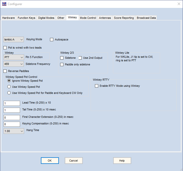
The Winkeyer tab is used to control functions of a K1EL Winkeyer chip. (or 100% compatible clone). Winkeyer is designed by K1EL and G3WGV. It is only active when the Winkeyer box has been checked on a serial port, and that port (whether real or virtual), has been connected either to a stand-alone keyer or to a device that embeds the Winkeyer chip, such as various MicroHAM and RigExpert products. Consult your unit’s manual along with the Winkeyer chip manual for more information on these settings.
To set up a port for a Winkeyer (or for a device that embeds a Winkeyer chip), select the COM port number that Windows has assigned to the Winkeyer, check the CW/Other check box for that port, click on the Set button, and check the WinKey check box. You do not need to change any of the other settings on the port setup dialog.
Winkeyer is fed ASCII characters from N1MM Logger (via COM or USB Ports), and converts the ASCII to timed CW. The pot speed range is from a minimum of 10 wpm to a maximum of 55 wpm. Winkeyer can also be used to control PTT. Winkeyer PTT can be used on modes other than CW. Note: This only works for Winkeyer versions 10, and 21 and greater.
Normally only the KEY1 and PTT1 outputs on a Winkeyer 2 or later are used. There is no provision for selecting KEY2 or PTT2 outputs instead, with two exceptions. The first exception applies in SO2R, where there is a capability to use KEY2 and PTT2 from the second Entry window for the second radio – see the Use 2nd output option below. The second exception relates to the option with a Winkeyer 3.1 of using any of the four outputs for FSK keying in RTTY – see the Select Winkey RTTY Keying Port option below.
Winkeyer Field Descriptions
- Keying Mode – Select the keying mode. Choices are: Iambic A, Iambic B, Ultimatic and Semi-Automatic. The default is Iambic B
- Autospace – Select when the autospace feature should be used. When using the paddles to send, if a pause of longer than one ‘dit’ time is detected, THREE dit times of pause will be inserted before the next character. See the manual for more information
- Pot is wired with two leads – This option applies to Winkey version 1 only. Select when the potentiometer on the board is wired only with two instead of three wires. Under normal operation, leave unchecked. Unless you’ve built the keyer yourself, or your keyer vendor recommends this, leave unchecked
- Pin 5 Function – Valid only for Winkey version 1. Select the function of pin 5. Unless your keyer’s manual tells you otherwise, the default of PTT is likely what you want here. The Winkeyer manual is also a good reference. The choices are:
- PTT (default)
- Sidetone
- 2nd CW (second output, do not use for SO2R – see below))
- None
- Sidetone Frequency – Select the Winkeyer’s sidetone frequency. The default sidetone frequency is 469 Hz
- Reverse Paddles – Reverse the left and right paddle
- Winkey Speed Pot Control – Three options:
- Ignore Winkey Speed Pot (when N1MM+ is running)
- Use Winkey Speed Pot (matches the N1MM+ speed to the pot setting)
- Use Winkey Speed Pot for Paddle and Keyboard CW only (enables QRS for manual CW)
- Lead Time – Set the lead time value in 10ms Increments (up to 2.55 seconds). This value reflects the amount of time that the Winkeyer PTT will be asserted BEFORE keying commences
- If when sending CW you are missing the first dot or dash, or if paddle-sent CW doesn’t seem responsive (again, missing the first character) set this to at least 10 mSec
- NOTE that this field denotes 10 mSec intervals — ‘1’ in this box means 10 mSec
- If Pin 5 function is set to PTT, set this value to at least 1 (10 mSec)
- Tail Time – Sets the tail time in 10 mSec Increments (up to 2.55 SECONDS). This value reflects the amount of time that the Winkeyer PTT line will be held after keying stops. Tail Time = 1 results in a tail time equivalent to sending one extra dit (Winkeyer v2.2; 10 msec in earlier versions of Winkeyer). Tail Time = 2 adds 10 msec to that, Tail Time = 3 adds another 10 msec, and so on. If Tail Time is set to zero, then Hang Time is used instead
- First Character Extension – Sets the extension time in 10 mSec steps (up to 2.55 seconds). Normally ONLY used with older, slower-keying rigs at speeds above 25 wpm, this setting will add time to the first element sent to help with the lack of T/R speed of those rigs. This value is usually set by experimentation. See the Winkeyer manual for more information on setting this value
- Keying Compensation – Normally only used with high speed (>30 wpm) QSK operation. Adds time (in 1 mSec increments) to both dashes and dots to adjust for rig switching delays (however slight). See the Winkeyer manual for more information
- Hang Time – Provides a CW speed-dependent means of holding PTT during CW sending from the paddle. Hang Time can be used to set a CW-speed dependent delay of 1, 1.33, 1.67 or 2 letterspaces (not dit spaces) after the last paddle closure. The Hang Time setting always applies to paddle-sent CW. For computer-sent CW, Hang Time is only used if Tail Time is set to zero. See the Winkeyer datasheet for more detailed information
- Winkeyer 2
- Sidetone – Gives a sidetone when sending CW (both when using a paddle and from computer input)
- Paddle only sidetone – Gives a sidetone only when sending by paddle
- Use 2nd output – The Winkeyer 2 has two sets of keying outputs, but normally only the KEY1 and PTT1 outputs are used. However, in SO2R, if the “Use 2nd output” option is checked, then when the transmit focus is in the second radio Entry window, CW and PTT will be switched to the KEY2 and PTT2 outputs. This is convenient for minimal CW SO2R, because no additional hardware is needed to switch CW and PTT between radios. You’ll still need to do something about the received audio switching, though. Select this option for SO2R operation using both outputs. In SO2V or SO1R, this option does not support CW operation from the second set of outputs, but it can be used for RTTY operation with a Winkeyer version 3.1 or later using an output connector other than KEY1 (see below)
- Enable RTTY Mode using Winkey – (Winkeyer version 3.1 or later only) Check this option and select Winkey as the TU Type under the Digital Modes tab to use the Winkeyer for RTTY FSK keying
- Select Winkey RTTY Keying Port (only visible if Enable RTTY Mode using Winkey is checked) – use this to select one of the other Winkey outputs (PTT1, KEY2 or PTT2) for RTTY. The Use 2nd output check box must also be checked to enable KEY2 or PTT2
Speed setting is done just as with other keying methods. The PgUp and PgDn keys will increase or decrease the speed (default is 2 WPM steps). You can also overwrite the value in the speed window, or use its up/down arrows. Shift+PgUp/PgDn increases or decreases the speed by a larger amount (default is 4 WPM). Both step size values are user programmable and can be set using the Configurer’s Other tab.
If the option to ignore the speed pot has not been selected, setting the speed using the speed control pot changes BOTH the paddle speed and the N1MM sending speed. Setting the speed using the entry window changes both the paddle sending speed and N1MM sending speed but ONLY UNTIL the next time the speed pot is adjusted, i.e. the absolute position of the speed pot then overrides any changes made in the entry window.
CW weight for Winkeyer can be set on the Other tab, but is not usually changed from the 50% default.
Mode Control Tab
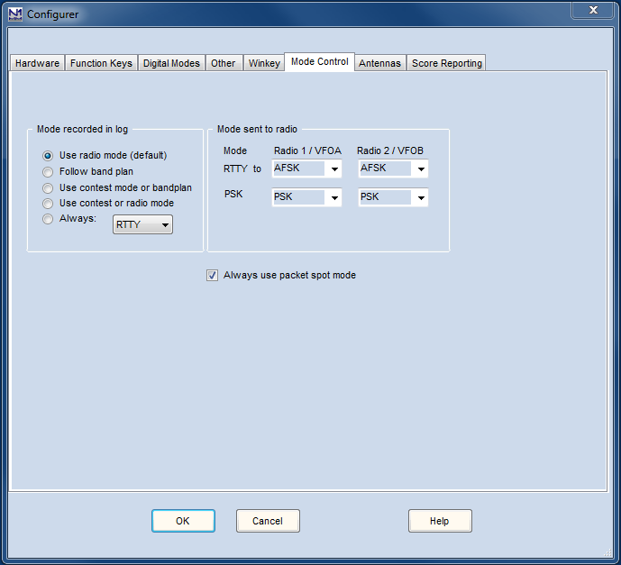
The mode control tab determines how (and whether)the mode will be controlled on the connected radio, whether the program sets the mode when changing frequency or not, and what mode it changes it to. This dialog also gives you control over the mode used when contacts are logged.
Mode logged vs. Radio mode
In an ideal world, the mode in the log, the radio’s mode and the mode in the software would all be the same. For traditional voice and keyed CW modes (CW, USB, LSB, AM, FM) this actually holds true. With the obvious exception of radios that do not support all of these modes, there is a one-to-one correspondence between the names of the modes on the radios, in the software and in the log. If these were the only modes that existed, it would always be possible to change modes on the radio and have the software follow (or vice versa) without risk of confusion or error, and there would be no need for mode control configuration settings.
However, when digital modes are brought into the picture this one-to-one correspondence breaks down. Any SSB-capable radio can be used for digital modes using a sound card, even if the radio itself does not have any native digital modes. This results in a many-to-one relationship (many different modes in the log can map to a single mode on the radio). In the case of RTTY, some radios have a native RTTY mode using FSK keying, and when it exists, this mode is uniquely associated with RTTY and not with any other digital mode in the log. However, the reverse is not true; depending on the hardware configuration and the operator’s choice, RTTY in the log may correspond with either RTTY or SSB on the radio. In the case of some radios, there may also be an additional mode or modes in the radio tailored either specifically for AFSK RTTY or for sound-card digital modes generally. Radio manufacturers use a bewildering and inconsistent variety of names for these modes.
For information about mode control for your specific radio, go to Supported Radios . In particular, for the correspondence between the mode names used in the right-hand side of the Mode Control window in the Configurer and the names used by the radio’s manufacturer, see the Digital Mode Mapping table. See the text box below called “Digital Mode Selection” for more details.
Because of this breakdown in the one-to-one correspondence, a radio-first priority system cannot be imposed in all situations – once digital modes are involved, setting the mode on the radio does not always uniquely identify the mode that should be logged. Instead, the primary rule is “software first”. Setting the mode in the software always controls what the radio does. You can select the mode in the software simply by typing the name of the mode (CW, SSB, USB, LSB, AM, FM, RTTY, PSK) into the entry window in the callsign box and pressing the Enter key. Provided the mode you have chosen is supported by the contest (this is determined by the Mode category in the contest setup window), the software and the radio will switch to the mode you have commanded, and that is the mode that will be logged, When the MMVARI or Fldigi digital engine is used, the specific digital mode logged will depend on what mode has been selected within the digital engine. Since not all radios use the same radio mode for digital modes, there are settings in the right side of the mode control configuration window that determine which radio mode is used for each of RTTY and PSK.
Automated Mode Switching
Despite the lack of a complete one-to-one correspondence between the modes in the log and in the radio, there are many situations where some degree of automated mode switching is possible, based either on the radio’s mode or on the frequency, and within the limits imposed by the current contest setup (i.e. what modes are supported within the current contest). The settings that control whether this kind of automation is used, and on what basis, are in the left side of the mode control window.
One of these options is to use the band map. You may be able to use this within a single mixed-mode contest where the modes are kept well-separated in frequency. Unfortunately, this doesn’t work in all situations. During major CW contests, for example, CW may be used pretty much throughout the normal digital sub-band. On the other hand, during a major RTTY contest you may find RTTY being used on frequencies that would normally be considered to be CW frequencies. For this reason, using the band map to determine the mode is not a foolproof set-and-forget option. Depending on the modes supported by your radio and the nature of the particular contest(s) you are operating in, you may need to choose one of the other options.
Digital Mode Behavior is Different
There is a difference in mode control behavior between the situation where the DI window and digital engine window are open and the situation where they are closed. This is due to the way serial ports are used by the digital engines and by the Logger. The digital engines are separate processes from the rest of the Logger, and a single serial port cannot be shared between two processes. Since serial ports can be a scarce resource in a complex contest station, the Logger allows time-sharing of serial ports between digital (FSK & PTT) and non-digital (CW & PTT) uses. It does this by switching the ports between the processes depending on whether the DI window is open or not. When the DI window is opened, serial ports that have the Digital box checked in the Configurer are closed by the Logger so that they can be opened by the digital engine. When the DI window is closed, these ports are released so that the Logger can open them for use in other modes.
Thus, whether the DI window is open or closed can make a significant difference to the hardware configuration. Whenever a serial port is time-shared between the Logger and a digital engine, that port cannot be used for PTT or CW keying in non-digital modes while the DI window is open.
In order to support the wide range of possible hardware configurations in a hardware-independent fashion, mode control in the Logger depends on whether the DI window is open or not. When the DI window is closed, radio-first mode control works between non-digital modes, but switching the radio mode to (or through) a digital mode or tuning the radio’s frequency into (or through) a digital band segment does not open the DI window and switch the software to digital mode. To switch into a digital mode, the DI window must be opened from the software. This can be done by using the Entry window to select RTTY or PSK mode in a contest that supports digital modes, or by using the Window > Digital Interface menu item.
Once the DI window is open, changing modes on the radio does not close the DI window and the software does not switch out of digital mode, which means that radio mode-driven mode control does not work when the DI window is open. Mode changes in this state must be performed from the software. If the software is commanded from the Entry window to use a non-digital mode, the DI engine is closed by the software in order to free up any time-shared ports for the Logger to use.
Mode Control Field Descriptions
- Mode recorded in log – Set how to determine the mode that will be entered in the log
- Use radio mode (default) – if the DI Window is not open, the mode is determined from the radio’s mode setting. If the DI Window is open, the mode used depends only on the digital engine and not on the mode received from the radio, as follows:
- In digital modes, the mode in the log will be RTTY if using the MMTTY or 2Tone engine or a TNC
- When using the MMVARI or Fldigi engine, the mode will be as selected in the MMVARI or Fldigi window (digital modes only for Fldigi)
- Follow band plan – the program will use the mode the bandplan gives for the frequency. For CW and Phone, this affects both what is entered in the log and what happens when you click on a spot in the Bandmap or the Available Mults and Qs window, but does not switch the radio automatically to a digital mode if you click within a digital band segment.
- Use contest mode or bandplan – In a single-mode contest, that mode is both logged and sent to the radio. If the contest is mixed mode (e.g. the Russian DX Contest) the bandplan is followed as above.
- Use contest or radio mode – In a single-mode contest, that mode is both logged and sent to the radio. In a mixed mode contest, the radio’s mode is used.
- Always: – always log the mode selected here (CW, SSB, RTTY, PSK31, PSK63, PSK125) regardless of the mode set on the radio.
- Use radio mode (default) – if the DI Window is not open, the mode is determined from the radio’s mode setting. If the DI Window is open, the mode used depends only on the digital engine and not on the mode received from the radio, as follows:
When you use the “Follow band plan” option for the Mode recorded in the log, it is imperative that the sub bands be set correctly in the Bandmap window, as the program will log contacts using the mode from the band plan as configured in the Bandmap window regardless of the mode you were actually using. Failing to set the sub band limits appropriately in the Bandmap window is a frequent cause of logging errors.
- Mode sent to radio – Select how to determine the mode sent to the radio
- This applies only for digital modes, including FT8/FT4, PSK31/PSK63, and RTTY. See the note below for details
- The row called RTTY is for RTTY only, since RTTY often uses a different mode in the radio from other digital modes.
- The row called DIGI (starting with version 1.0.7937; it was previously called PSK) is for all digital modes other than RTTY, including FT4/FT8 as well as PSK31/PSK63, etc.
- If your radio has a special mode(s) for sound card digital modes, the mode labels in the pull-down list probably won’t match the mode names in your radio. See the text box below.
Every radio seems to have a different range of choices and names for digital modes. Some radios have no modes specialized for digital modes, some have only one digital mode for FSK RTTY (for sound-card digital modes, you use USB or LSB), some add to this a separate mode intended for sound-card digital modes like AFSK RTTY, PSK31 and FT8, and some radios have three separate digital modes for FSK RTTY, AFSK RTTY, and other sound-card digital modes like PSK31 and FT8. There may also be two versions of each of these, one “normal” and one “reverse” (opposite sideband). Every manufacturer uses different names for these specialized modes.
For simplicity, N1MM Logger has its own radio-independent terminology. The Logger uses RTTY for the radio mode normally used for FSK RTTY (which is usually but not always called FSK or RTTY on the radio). If the radio has a mode that is designated for AFSK RTTY, the Logger calls it AFSK (your radio manufacturer may have a different name for this, such as LSB-D or PKT-LSB). AFSK-R is the “reverse” of this AFSK mode, i.e. on the upper sideband instead of LSB (and might be called USB-D or PKT-USB on the radio). If there is a mode intended for sound card data modes that is different from the AFSK-R mode (such as the DATA A mode in the Elecraft K3/K3S), it will be called PSK in the Logger. Not all radios have all of these modes, so not all choices will necessarily be available, depending on what radio(s) is/are configured.
The translation between the mode name used on the radio and the mode name used in N1MM Logger is described at Click here to see the table
For RTTY, if you are using FSK, you should normally select RTTY. If you are using AFSK, you should normally select AFSK or LSB/USB, depending on whether your radio offers a specialized AFSK mode or not.
For other digital modes (including PSK and WSJT modes), the choice would normally be one of: PSK (if available, e.g. Elecraft K3/K3S), AFSK-R (on some radios, e.g. IC-7300), or USB (older radios that do not have a dedicated mode for sound card digital modes).
Always use packet spot mode check box:
If this box is checked, then clicking on a spot in the Bandmap (or jumping to a Bandmap spot using the keyboard) may change the mode of the radio, depending on whether the spot notes describe the mode or on the sub-band settings in the Bandmap window, and on whether the Mode Category in the Contest Setup dialog includes the packet spot mode as determined either by the spot notes or by the band plan settings. In a single-mode contest, you probably do not want to change the radio’s mode as a result of clicking on a spot, and so this option should not be checked. In a multi-mode contest or for general logging, you might want to allow the packet spot mode to change the mode of the radio, but in this case it is important to set the CW, Digital and SSB sub-band limits appropriately in the Bandmap window, otherwise spots without spot notes (e.g. many human-generated spots) may cause the radio’s mode to change in an unwanted manner.
Antennas Tab
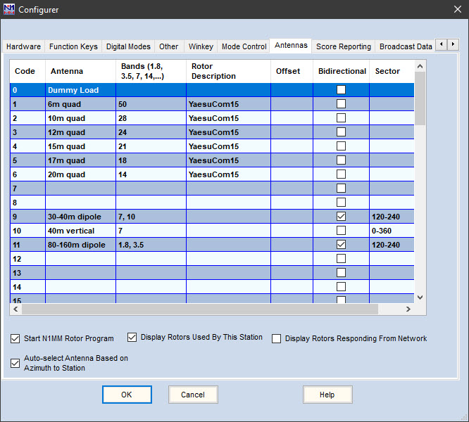
The Antennas Tab defines how antennas can be selected by the program, if you have appropriate hardware, and also controls the rotor program. The example above illustrates the features of this tab.
The program uses a variety of antenna-related interfacing options, depending on your hardware and preferences. For example, antenna selection can be controlled by using a band decoder in conjunction with BCD values 0-15 on a real LPT port. Note that USB-to-parallel adapters do not work in this or other parallel port interfacing functions, because they do not allow program control of individual pins on the port.
Antenna selection can also be controlled by one of two serial port protocols, the proprietary MicroHam protocol and the Open Two Radio Switching Protocol (OTRSP). Rotators can be controlled either by using the N1MM Rotor Program, or by various third-party software packages that make use of UDP broadcasts sent by N1MM Logger+.
Unlike most transceivers and some logging software, N1MM does not map prescribed bands to its antenna output value. Instead, N1MM maps antennas to outputs ranging from 0 to 63. You can still map bands, but the antenna approach is much more powerful. It supports multiple antennas per band, stacks, and multiple bands per antenna. See the screen shot above and the Field Descriptions below. You can have multiple antennas for a band and use Alt-F9 to cycle through them.
Antennas Tab Column Descriptions
- Code – The code which will be presented on the LPT port as binary coded decimal output, using pins 9, 8, 7 and 2. It is also the code sent to an OTRSP device, in the OTRSP AUX message.
- The codes themselves are pre-determined, ranging from 0 to 63. Note that if you are using an LPT port with BCD output, the maximum represented values are from 0- 15 (4 bits). In the example above, no antenna for Code O is defined – this is because in that case that code is used to select automatic operation from the front panel of the remote antenna switch.
- Each row in this table, and thus each code, represents ONE ANTENNA, although it can support more than one band. For example, one code can select a tri-bander that is defined for 10, 15, and 20 meters.
- Most stations will use a Band Decoder to receive the code sent from N1MM and translate that single code into activation commands for remote antenna switches. Google search for “ham radio band decoders” to see the list of many available devices.
- Antenna -Text to describe the antenna. This text will appear on the status bar of the Entry window when you change bands or switch antennas for a given band. Use Alt+F9 to toggle through all the antennas defined for the current band. This text listing the current selected antenna will appear in the center-right side of the N1MM Entry Window.
- Bands – The bands on which this antenna will be selected
- List bands in MHz. The valid band text list is: 1.8, 3.5, 5, 7, 10, 14, 18, 21, 24, 28, 50, 70, 144, 222, 420, 902, 1240, 2300, 3300, 5650, 10000, 24000, 47000, 76000, 142000, 241000. If the antenna supports more than one band, separated bands by commas. See the screenshot above with dual band dipoles on antennas 30/40 meters and 80/160 meters. Note that the first antenna in the table will always be selected when changing to a band. Press Alt+F9 to select other antennas that are defined for the same band. In the screenshot above, a station on 40 meters would use Alt+F9 to toggle between the dipole and vertical antenna.
- An antenna may be used on any number of bands
- Rotor Description – enter the description as defined in setting up the rotor program. It must be exactly the same in both places, because these names make the connection between the two programs.
- More than one rotor can be selected (separate using commas), for example to turn a stack where more than one rotor is involved.
- Offset – This offset is added to the rotor position to determine the antenna position. This is useful for antennas that are mounted at 90 degrees for pattern interference reasons, or for antennas that have simply turned some in the wind over the winter. The offset can also be entered for the selected rotor in the rotor program
- Bidirectional – Check this box if the antenna can be set bidirectional (0 = not bidirectional, 1 = bidirectional) (For example: dipoles and Steppir beams)
- Sector – For stationary (non rotating) antennas. Describes the compass headings of the antenna’s transmitted pattern, separated by a dash. For example: 45-90. Define an omni-directional antenna as 0-360. N1MM will automatically recognize a bi-directional antenna as covering the defined sector and its opposite direction. See option description “Auto-Select Antenna Based on Azimuth to Station” below.
Options in the Antenna Dialog Window
- Start N1MM Rotor Program – Start the N1MM Rotor program automatically from the N1MM Logger+ main program. You will need to stop it manually
- Display Rotors Used By This Station –
- Display Rotors Responding From Network –
- Auto-Select Antenna Based on Azimuth to Station – Selects an antenna (Code) based on the antenna that 1) matches the band and 2) matches the direction to the location of the station entered in the Entry Windows callsign field. For stations with multiple stationary antennas aimed at different targets (For example: Europe, South America, Asia), the selected antenna will be that which falls in the transmit pattern of antennas for that band. If there is no directional match, N1MM will simply choose the first antenna listed for a band.
HINT: Define a catch-all antenna with sector 0-360 as the last listed antenna for a band. If no stationary antenna supports the azimuth to a station, N1MM will defer to the default 0-360 antenna. Example 1: Big Gun station has 20 meter stationary antennas for EU and SA, and a rotatable beam for other directions. Define the rotatable beam after the other 20 meter antennas with a Sector = 0-360. Example 2: Little Pistol station has a bi-directional 40 meter dipole that favors North-South, and a vertical for other directions. Define the dipole as 120-240, and the vertical as 0-360. Example 3: Low-band station has an omni-directional vertical on 160 meters and four receive beverages for North (325-45), South (135-225), East (45-135) and West (225-325). Define four “antennas” for 160 meters, and use your band decoder to select the vertical plus the corresponding directional beverage.
To view a short video that describes the difference between alt+F9 and Sector-Based antenna switching, click HERE
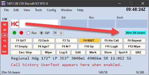
The selected Antenna is highlighted in the Entry Window when changed
Score Reporting Tab
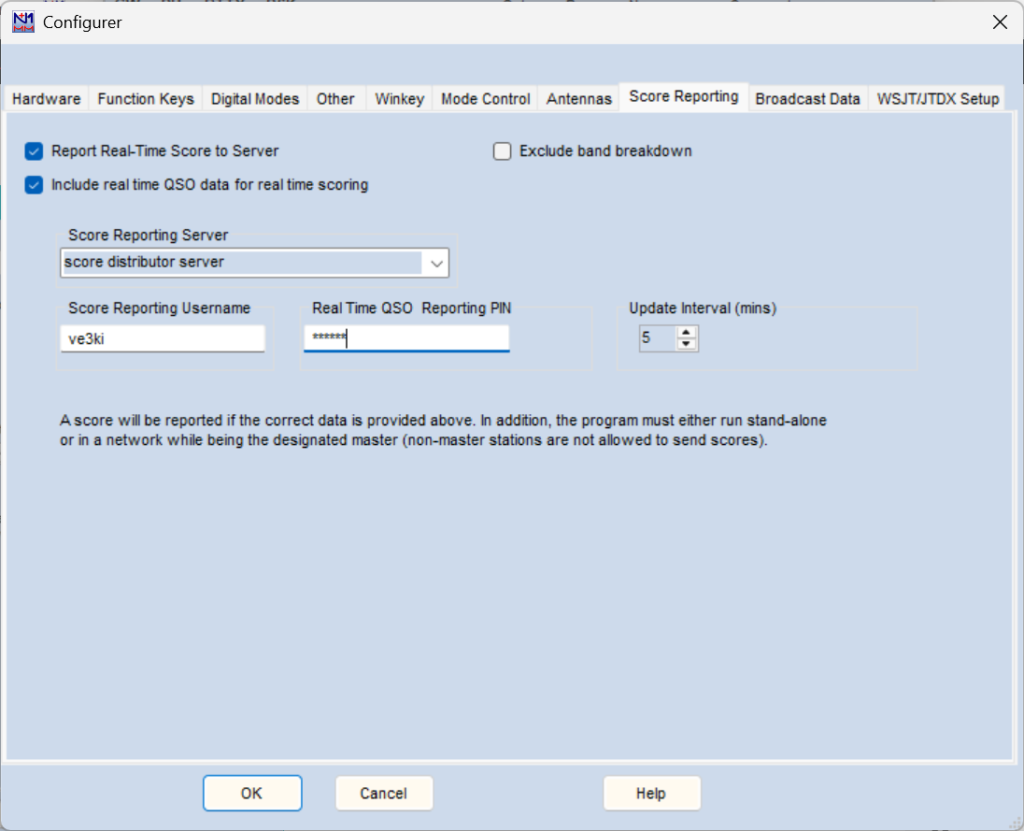
In N1MM Logger+, the Real-Time Score Reporting function has been integrated with the rest of the program. Instead of checking a box on the Other tab of the Configurer to start it, it now has its own tab in the Configurer.
Following, left to right, are the options you will need to set up to use it.
- Report Real-Time Score to Server– this checkbox is checked to start reporting real-time scores. It will stay selected until you uncheck it.
- Exclude band breakdown – if you feel that for competitive reasons you don’t want to disclose your band breakdown, revealing your band-change strategy, check this box.
- Include real time QSO data for real time scoring – this will send QSO data to the real-time scoring website (experimental: performs log cross-checking in real time).
- Score Reporting Server – The server name is editable. One of the entries in the pulldown list is “score distributor server”. For most users, this is the appropriate choice, as it forwards reported scores to all online scoreboards. If the “Include real time QSO data …” checkbox is checked and the contest is one of the ones supported by the real-time scoring website, QSO data will be forwarded to that website for cross-checking in addition to the regular score reporting to the scoreboard websites.
- Score Reporting Username and Real Time QSO Reporting PIN (formerly called Score Reporting Password; only appears if the real time QSO data checkbox is checked) – For security reasons, the real time score reporting web sites require that you register your callsign and a system-assigned PIN. Once you have done so, enter them in the textboxes provided.
- Update Interval – Adjustable from 2 minutes to 60 minutes.
To be sure that your scores are being sent, check just above the lower text pane in the Info window. Each time a score is sent and acknowledged by the server, you’ll see a notification there.
Broadcast Data Tab
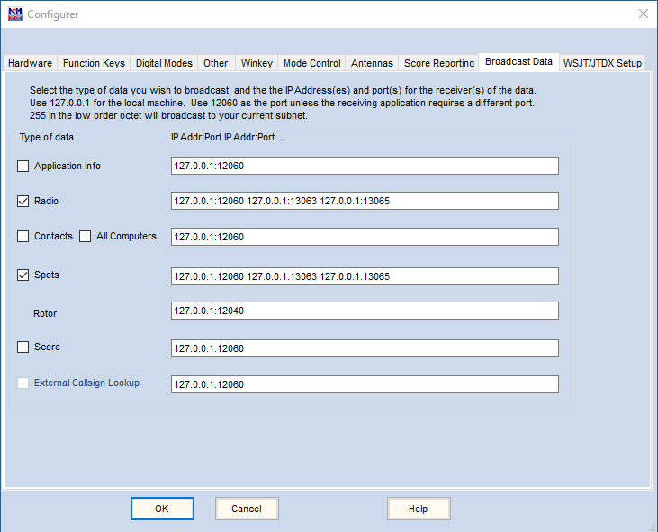
External UDP broadcasts contain data communicated to other application programs running either on the same computer or on a different networked computer. The use that is made of the broadcast data depends on the capabilities of the receiving application program. Some examples include the sending of score data to an online score reporting website, bearing data to a rotor control program, and contact data to a general-purpose logging program (either for logging purposes or to facilitate lookup of other data available to that program). The data contents of these broadcasts are described in detail in the Appendices > External UDP Broadcasts page.
To enable external UDP broadcasts, before December 2015 some lines needed to be added manually to the N1MM Logger.ini file, This editing function has now been incorporated in the External Broadcasts tab of the Configurer, shown above. If you had been using External Broadcasts before this change, the contents of your existing External Broadcast section should be reflected on the tab. For example, if you have IsBroadcastContact=True is in your existing ini file, then the Contact box on the tab should be checked.
To set up your UDP broadcasts, you need to decide which broadcasts to enable, by checking the relevant box, and then fill in the IP addresses and UDP ports to which you want each broadcast to go. Typically, UDP broadcasts are used to communicate with other programs, so begin by reviewing the documentation of the program you want to communicate with, to learn what port it wishes to receive data on. In most cases, the port number will be 12060, the default.
In filling in the IP Addresses and Port numbers for each broadcast, you need to put in the 4-part IP address, separated from the port number by a colon. Each IP/Port pair is separated from the next by a single space, as shown in the example on the tab.
You can start with IP address 127.0.0.1 (the PC you are running N1MM+ on) and add other PCs’ IP addresses. For each receiving computer, separate the address and a port number with a colon (:), as in the illustration. Note that you can also specify the Windows computer name (up to 15 characters long) instead of the IP address. This is a recommended approach for local computers.
Typically, home networks are all one “sub-net.” Most home networks use either 192.168.0 or 192.168.1 to designate their “sub-net”, plus a 3-digit number in the last section that identifies the specific computer. Usually, these numbers are automatically assigned by the router through something called DHCP, though you may have the option to fix them in the router software., and doing so will help to avoid confusion later .
You can send UDP broadcasts to all the IP addresses in the subnet by specifying 255 for the last section, or “octet”. For example, 192.168.1.255 will send to all computers that are in the 192.168.1 subnet. Be sure you only use 255 in the last section or octet, because if you put that number in one of the earlier/higher-order sections, you will risk broadcasting to the internet. While eventually the packets will be discarded by the internet, it will not endear you to your ISP.
Broadcast Data Details
When properly configured, N1MM Logger+ sends external UDP packets to other applications. Details about those packets can be found in the >Appendices >External UDP Broadcasts section of this documentation.
All Computers
This command is useful only in Networked Computer mode. When checked, together with Contact, at any station on the network, that station will rebroadcast every contact that it receives to the UDP port specified. The XML format is the same as for Contact.
Exercise caution when using this feature. Multiple, misconfigured stations with All Computers checked could result in a circular network path.
Spots
N1MM Logger+ sends external UDP packets about spots (including spots generated internally as well as spots received from telnet clusters) to other applications. Details about these packets can be found in the >Appendices >External UDP Broadcasts section of this documentation.
Log data input from other programs
Note: In version 1.0.7860 and later, these settings have been moved from the Broadcast Data tab to a new WSJT/JTDX Setup tab in the Configurer.
N1MM+ can accept log data from other programs, either using UDP packets (JTAlert, WSJT-X, JTDX), or TCP packets (JTDX). To enable this in N1MM+ version 1.0.7845 or earlier, you need to check the Enable box in one of the two labelled sections near the bottom of the window. You may also need to do some configuration setup in the sending program, WSJT-X or JTDX (JTAlert does not need to be specially configured). If both programs are running on the same computer, the default IP address and port number should work, but if necessary for more complicated setups, the IP address and port number can be changed here.
If WSJT-X or JTDX is to be called up from the Window > Load WSJT/JTDX menu item in the Entry Window, then the upper Enable check box must be checked, and the port must be set to 2237 (unless the port has been changed in the WSJT-X settings). In the WSJT-X Settings window under the Reporting tab, in the area called “UDP Server”, the “Accept UDP Requests” check box must be checked.
If the JT-modes program is to be run independently rather than called up from the Window menu, as is required by JTAlert and some WSJT “clone” programs that cannot be called up directly from the Entry Window’s Window > Load WSJT/JTDX menu (because they do not support the UDP server method that N1MM+ uses for this), then it may be necessary to change the port number to 2333 (depending on the program). In WSJT-X, there is a :Secondary UDP Server” area (formerly called “N1MM Logger+ Broadcasts”) at the bottom of the Settings window under the Reporting tab. When using WSJT-X from inside N1MM+, this area is not used (the Enable button in this area should be unchecked), but when WSJT-X (or other similar program) is run independently, the Enable button may need to be checked and the port number in the N1MM+ Configurer changed to match the port number in this area.
For more information on setting up and operating with WSJT-X or JTDX, see the >Window >WSJT Decode List page in this manual.
Note that if you are calling WSJT-X or JTDX up from within N1MM+, you cannot use JTAlert at the same time. This is because it uses the same UDP port that N1MM+ uses, and the port cannot be shared.
Audio Tab
This tab is no longer available in current versions of the Logger. It exists only in the older Windows XP version of the program.
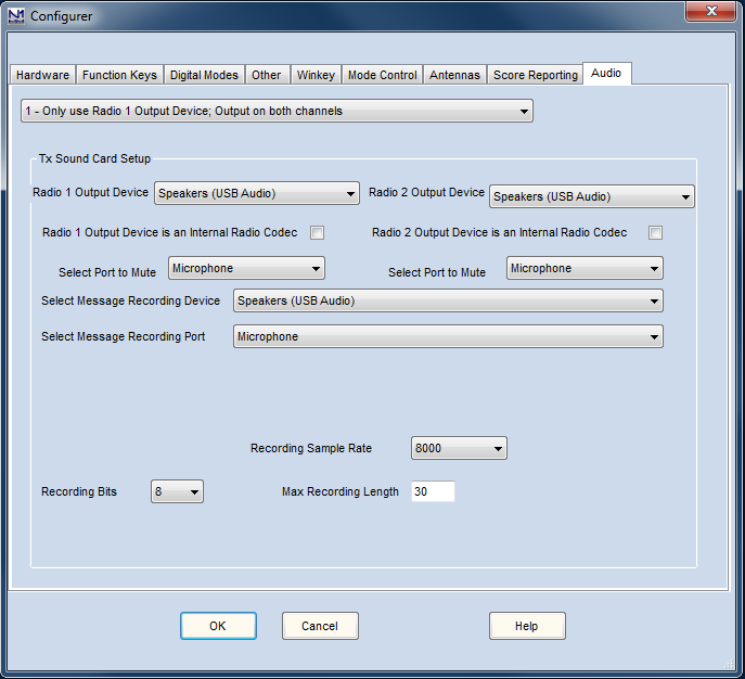
If you have checked the “Use Logger+ audio” menu item in the Entry window’s Config menu (not available in Windows XP), the “Audio” tab will not appear in the Configurer. In its place, use the “Logger+ Audio Setup” menu item in the Config menu to set up Logger+ audio.
Any time you change the Default sound card in your Windows Control Panel while N1MM Logger+ is running, you must shut N1MM Logger+ down and re-start it. Otherwise, the program and the operating system may be on “different pages”, and it can cause audio functions not to work or to work strangely. Moreover, any time that you change the Windows Default sound card, you will have to come back to this tab and reset your audio options. You can imagine how we found this out!
Introduction to Audio & Sound Cards
Users of N1MM Logger Classic may recall when we deleted the QSO recording function from this tab in favor of a separate recorder, QSOrder by K3IT. QSO recording is configured there, and not in the Configurer. Currently, the Audio tab in the Configurer only controls settings that are used for playback of stored voice messages and for recording those messages. This includes on-the-fly re-recording, such as might be required in contests for split SSB operation on 40 meters, for example.
If your computer is using Windows XP SP3, then this audio setup is the only one available to you. If you are using a later operating system, you have the option of using either this setup or a new Logger+ audio configuration dialog, which is found on the Config menu of the Entry window. If you check the option on the Config menu, you will note that the Audio tab on the Configurer will no longer be visible, and you will need to use the Audio configuration dialog which is on the Config menu. Conversely, if you are using XP, the Config menu entries will disappear. Full details on the newer Logger+ audio will be found in the description of these menu items.
If you are setting up this tab for the first time, a good beginning is to familiarize yourself with your computer’s sound card(s). At the same time, you can assure yourself that all of your computer’s audio settings are correct for recording from your microphone and playing back to your radio’s audio input (microphone or line). A step-by step procedure for doing so is in the Interfacing section of Getting Started. A much more detailed treatment of the use of stored messages in SSB contests is here.
Audio Output
- 1 – Only use Radio 1 Output Device, Output on both channels
- One radio and one sound card, to play stored messages, record or re-record messages and mute the microphone when playing stored messages.
- Use this setting with two radios if you are using separate sound cards for the two radios.
- 2 – Two Radio, Output left channel on left radio, right channel on right radio
- Use this setting if you are using a single sound card to play stored message files to two separate radios in SO2R (one channel for each radio)
Tx Sound Card Setup
This is where it gets a little messy, largely because of differences in the way Windows XP handles sound cards, versus the way they are managed in Vista, 7 and later. Let’s look at that a bit.
In Windows XP,
- Select Radio 1 Output Device – Select the sound card to use for sending stored messages (.wav files) on Radio 1.
In Windows Vista and later operating systems, the pull-down list shows output (playback) ports available on the computer, including those on multiple sound cards if more than one is available.
If there is a CODEC built in to Radio 1, choose that (CODEC is used here and elsewhere in this manual as a synonym for sound card). If not, choose the Line Out or Speaker Out port on the sound card that is connected to Radio 1’s audio input.
In Windows XP, the pull-down list shows sound cards available on the computer; choose the built-in radio CODEC in Radio 1 or the sound card whose Line Out or Speaker Out port is connected to Radio 1’s audio input.
- Select Radio 2 Output Device – Same as for Radio 1.
CODEC
Built-in sound card capability is just starting to appear in new-generation transceivers.
- Radio 1 Output Device is an Internal Radio Codec – Check this box if you are using a CODEC built into Radio 1 instead of a separate sound card
- Radio 2 Output Device is an Internal Radio Codec – Check this box if you are using a CODEC built into Radio 2 instead of a separate sound card
Select Port to Mute
Typically, this is used to mute the microphone during stored message playback, so you would select Microphone from the drop-down list. The two options are for Radio 1 and 2, left to right
Select Message Recording Device
Select the sound card to use for recording stored messages for later playback on either radio. In Windows Vista and newer versions, the pull-down list displays playbackports available on the computer. Choose a port that is on the sound card that you will be using to record SSB messages. In Windows XP, select the sound card that will be used to record SSB messages.
You may ask what playback ports have to do with recording – we’ll just have to ask you to trust us on this one. you must select a device in order for recording ports to appear (see below).
Select Message Recording Port
Having selected the sound card device, use this pull-down list to select the recording port you will use on the selected sound card device to record SSB messages. This is normally the microphone input
Recording Bits and Sample Rate
- Recording Bits – this setting determines how your sound card digitizes analog audio levels – generally, the lower the bit rate the smaller the file but also the lower the fidelity
- Recording Sample Rate – This setting determines how your sound card digitizes analog audio__ frequencies. Select the sample rate to record. The lower the rate the smaller the files but audio quality will be less.
- Max Recording Length – Upper limit on the length of a recorded message, in seconds.
The Configurer lets you pick parameters that your sound card may not support. If you choose a parameter that is not supported by your card, you should see Error 4 in the status line of your Entry Window when you try to play back a message, but under some circumstances, this may not happen. Our best advice is to verify that sample rates match and test before the contest starts.
This can be tricky. Even though playback rate is not specified, some sound cards permit playback only of .wav files recorded at a given sample rate, such as 44.1 or 48 KHz. Make sure your recording parameters match those, or you will not hear any output from your recordings (don’t ask how we know).
WSJT/JTDX Setup Tab
Starting in version 1.0.7860, settings related to WSJT and JTDX that were formerly under the Digital Modes tab and Broadcast Data tab have been moved to a new WSJT/JTDX Setup tab in the Configurer:
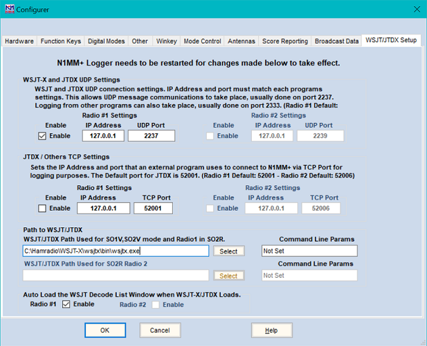
The top part of this page is where you set up the UDP port addresses for communicating with WSJT-X or JTDX. The IP address is the IP address of the computer on which WSJT-X or JTDX is being run. In the most common situation where that is the same computer on which N1MM+ is running, the IP address is the internal loopback address 127.0.0.1. Starting with N1MM+ version 1.0.9600.0, support for multicast addresses (224.0.0.x or 239.x.x.x) has been included. This allows other programs such as JTAlert and GridTracker to communicate with WSJT-X in parallel with N1MM+. The same multicast IP address must be used in all of the intercommunicating programs (e.g. 224.0.0.1 for Radio 1, or in SO2R configurations, 224.0.0.2 for Radio 2).
In the normal configuration, when WSJT-X or JTDX is run from within N1MM+, the default port number is 2237. If you are in SO2R mode and using WSJT-X or JTDX from the second Entry window (EW1), you need to configure a different UDP port number for Radio #2 (EW2) (the suggested port number is 2239) – this port number will also need to be entered in the settings for WSJT-X or JTDX for the second Entry window, since the default 2237 will not be correct for this copy.
If you are using a JT-mode program that does not support the communications method used between N1MM+ and WSJT-X or JTDX and therefore cannot be called up from the N1MM+ Load WSJT/JTDX menu item, you may still be able to send log data from that program to N1MM+ on another UDP port (usually port 2333). If you are using one of these programs, set the UDP port for Radio #1 in the top part of this window to 2333 and ignore the other settings on this window.
If you are using JTDX, it needs to use a TCP port in addition to the UDP port. The settings for this are in the next part of the window (you can ignore these settings if you are using WSJT-X). When running an external program, such as JTDX, using TCP on the same computer as N1MM+, the IP Address will typically be the loopback address (127.0.0.1). When running an external program using TCP on a different computer than N1MM+, the IP Address will be the address of the internet interface on the computer running N1MM+, such as 192.168.1.101. The default TCP port for JTDX is 52001. In SO2R, the suggested TCP port for the Radio 2 copy of JTDX is 52006, and the port number in the JTDX settings for the second Entry window (EW2) will need to be changed to correspond.
The next part of this window is where the path to the WSJT-X or JTDX program is entered in order to enable the program to be called from the N1MM+ Windows menu. The recommended way to enter this path is to click on the Select button and then navigate in the File Open dialog window to the location of the wsjtx.exe or jtdx.exe program and click on the Open button. As illustrated in the screen shot, SO2R stations can make both paths the same. There is also a box on the right side of the window where other command line parameters may be entered; this is optional and in the majority of cases will not be used.
At the bottom of the page are two check boxes to enable automatic startup of the WSJT Decode List window when WSJT-X or JTDX is started up from the N1MM+ Window > Load WSJT/JTDX menu item. The second check box is only used for SO2R.
For instructions on using WSJT-X or JTDX together with the WSJT Decode List window, see the WSJT Decode List Window section of the manual.