-1- The Entry Window
Key Features
The Entry window is the main program window; it’s the “central control panel” for the program. Your entry window will be similar to this one:
Customizable Skins, Colors and Fonts
Note that while the colors and font sizes displayed here and in other screenshots mimic the original N1MM Logger Classic, Logger Plus provides for extensive customization of colors and fonts in every window, part of an effort to improve accessibility.
Which Entry window textbox has the entry focus?
in edit – provisional text based on e-mail from N1MM
Versions 1.0.5108 and after include a change to how Entry Window textboxes are highlighted to show you which has the entry focus. This is active in SO1V, SO2V and SO2R.
What inspired this change is that Win 10 is particularly bad at visual cues to show you which window is active. In Win 10, if the title bar is grayed, then the window is inactive. Problem is, some windows don’t have titles. Sigh. It’s probably possible to change this with the OS, but I doubt many will do it, thus the change.
Beginning with the version to be released Tuesday August 25, the Skins, Colors and Fonts Window will allow you to choose the old method of indicating focus, and two choices for background highlighting
corresponding to the two colors you have chosen for the Log window grid. It is important that your mult and dupe foreground colors are easily visible on the background that you choose. The default color scheme is pretty reasonable in this regard.
What is different in the new scheme is that only the textbox with focus, in the window with focus, will have a white background. The white textbox will always tell you where the next character you type will go. If neither Entry window has focus, then all the textboxes in both will show with a colored background. If you are working in another application, then you will need to use your mouse to bring focus back to N1MM+.
There is a bonus to this change. We spent a lot of time trying to get focus back to the Entry Windows in a sensible way when you use the other windows in N1MM+. With the EW textboxes flashing white/color, this focus behavior is made much more obvious. I would ask that you not complain about the focus movement behavior for a week or two because it has not changed with the “colorization”. Once you have acclimated to the new version, then it would be a good time to point out whatever inconsistencies there may be in the focus behavior.
Finally, in working on this improvement, I ran across this feature of Windows: http://www.howtogeek.com/194095/how-to-change-the-blinking-windows-keyboard-cursor-thickness/
It allows you to change the thickness of the cursor. I changed mine to 2. It’s much more visible without being obstructive.
Right-click Menu
In addition, this right-click menu is provided.
The first 5 choices affect the size of the entry window. Uncheck them to remove things in the window that you do not need.
“Show User Information”, if selected, will display Call History User Text.
The 6th option, Band Button Left Click Enabled, is on by default, but may be turned off. In a multi-op station, it may be helpful to turn off the left-click band change to prevent accidentally changing bands.
If you click on the 7th option, “Change Band Panel Display”, this dialog will appear.
Click the Default button to display the traditional contest bands (HF or V/UHF depending on contest), or all HF bands except 60M when using the DX general logging “contest.” Check individual bands to display only those bands. Note that if you select a single band contest on either HF or VHF, the Band Panel will continue to display the full list until you check the bands you want to have displayed.
There is an 8th menu item, “Show GMT Time”, which causes a GMT (UTC) clock to be displayed in the upper right corner of the Entry window.
Display of Check status
If the Check window is open and an exact match to the entered call-sign is found, a check will appear in the right end of the call-sign text box. The check is colored to match the call-sign color and reflect multiplier status – by default, the colors are green for double, red for single, blue for no multiplier but a workable station for QSO credit. A “?” appears if no match is found, unless you opt to turn that option off in the View Menu of the Entry window.
Band Panel
- There is one column of band buttons in the Band Panel for each permitted mode in the current contest, just to the left of the Call-sign textbox. The color codes shown, when a callsign has been entered, are for the currently-entered call-sign in the call-sign textbox. Green=”double mult” red=”single mult” blue=”not worked yet” grey=”dupe). These are default color choices – see the Skins, Colors and Fonts window, reached from the Config menu, to change these color codes throughout the program.
- The Band Panel modes are determined by the Mode Category set in the Contest Setup Dialog (File > New Log or Open Log), not by the mode of the radio or one entered in the call-sign textbox (\”CW\”, \”USB\”, etc.).
- Left click on a mode/band button to move the program to that mode and band; an attached radio will follow, to the last frequency you used on that band. The rounded rectangular box around “15 CW” in the illustration above is an indicator of that radio’s current band and mode, which may be useful during rapid band changes.
- To change the bands and modes displayed in the Band Panel, right-click on a blank area of the Entry Window and choose “Change Band Panel Display…”
- When not in Networked Computer mode, if you right click on a mode/band button, your radio will QSY to that band and mode, to the last frequency you used on that band, and the callsign of the last station you logged will be locally spotted (not sent out to the Internet). This feature is primarily intended for VHF contests where you may want to move a station to many band/mode combinations in quick succession.
- When in Networked Computer mode with a callsign in the Callsign textbox, if you right-click on a band/mode button, the callsign and frequency of the station you are working will be passed to the networked computer on that band. An Info window message will be sent to the recipient station, and the passed callsign will be placed on the recipient station’s Bandmap on its specified Pass frequency.
Action Button Row
- Esc:Stop – Immediately ends transmission of a stored message (all modes)
- Wipe (Alt+W, Ctrl+W)– Clears information about the current contact. You can also program this into a Function Key, using the {WIPE} macro, for one-keystroke operation. A second press will restore the information that was wiped out.
- Log It (Enter) – Writes this contact to the log. Disabled when in Quick Edit mode. If you have not filled in all needed exchange information, you will be prompted before logging will occur. You can use Ctrl+Alt+Enter to circumvent this \”editing\” function and log whatever you have entered, for correction later.
- Edit – Pops up the full Edit window to edit the last contact. Use Ctrl+Q (Quick Edit) as a convenient alternative. Greyed out when in Quick Edit mode.
- Mark (Alt+M) – Marks the current frequency in the Bandmap as being in use. Used when you don’t want to take time to enter the call of the station using the frequency.
- Store (Alt+O) – Spots on the Bandmap the call-sign you have entered in the Call-sign textbox. It will be shown in bold because it is self spotted. The Telnet Filter tab option \”QSYing wipes the call and spots QSO in Bandmap\” is an easier way to do this, whether you have worked the station or not.
- Spot It (Alt+P) – Spots either the callsign in the callsign textbox or the last QSO logged, if Telnet is active. See this section for more information.
- QRZ – Performs a lookup on QRZ.com of the call-sign in the Call-sign textbox, if your computer is connected to the Internet.
Function Key Panel
- F1 through F12 – Sends the associated CW/Digital text or .wav file, and executes any macros stored in the message. Right click on the buttons to open the Function Key Editor. Running and S&P modes each have 12 stored messages. Press Shift+F1 through F12 to send the Run message when in S&P mode, or vice versa.
Run/S+P (radio buttons)(Alt+U)
Switch between Run and S&P mode. This also switches between the Run (first 12) and S&P (second 12) messages in the .mc file (unless the second 12 messages are not present in the .mc file).
CW speed(PgUp/PgDn)
- The textbox shows the current CW speed. Either PgUp/PgDn or clicking the up/down arrows alongside the speed will change the speed. Only visible when CW mode is selected. The interval in WPM is set on the Other tab in the Configurer. Additional keystroke combinations for changing speed by a larger (secondary) interval may be seen under Key Assignments.
When using a Winkeyer, if you do not check “Ignore Winkey Speed Pot” on the Winkey tab in the Configurer, the program’s starting CW speed will be set by the Winkeyer speed knob. If you check that box, the program will start at the last CW speed used.
Entry and Transmit Focus – The Red and Green dots (“LED”s)
On the Entry Window below the left end of the Call-sign textbox you will see either a green or a red dot (LED), or both. The LEDs are visual aids that help you keep track of what is happening on each VFO/radio, particularly when operating SO2V or SO2R. This is part of N1MM’s continuing philosophy of letting the operator easily know what’s happening at any given time.
Green dot/LED – This VFO/radio has Entry focus – also known elsewhere in this manual as RX (Receive) focus or Keyboard focus. This means that any information entered by keyboard goes in that window, including function keys. Depending on your SO2R switching setup, it may also denote which radio you are hearing in your headphones.
Red dot/LED – This VFO/radio has the Transmit focus. When actively transmitting, the red LED turns to orange (default) or another color defined in the Manage Skins, Colors and Fonts window, reached from the Config menu. Note that the Transmit focus does not necessarily tell you which radio will transmit next; this depends on whether transmitting is initiated from the keyboard or by some other method. For example, if the red LED is in Entry window A, but the green LED is in Entry window B, pressing F1 will send CQ on radio/vfo B, because it has the Entry or Keyboard focus; the red LED will move to that window before transmitting starts, and remain in the active transmit color for the duration of the CQ before returning to the darker red color. On the other hand, if transmitting is initiated without using the keyboard (e.g. from an external paddle or footswitch), the transmit focus will not move.
The following table explains how certain keystrokes and mouse-clicks move the LEDs from one entry window to the other
| Action | Starting Condition | First Keystroke | Subsequent Keystrokes |
| Back-slash | Both in one Entry window | RX focus to other Entry window | Toggle RX focus between Entry windows |
| One in each Entry window | RX focus to other Entry Window | Toggle | |
| Pause | Both in one Entry window | Both to other Entry window | Toggle both |
| One in each Entry window | Both to Entry window with Transmit focus | Toggle both | |
| Mouse click (anywhere but buttons) | N/A | RX to clicked window | N/A |
| Ctrl+left arrow | Both in one Entry window | Both to VFO/Radio A | Nil |
| One in each Entry window | Both to VFO/Radio A | Nil | |
| Ctrl+right arrow | Both in one Entry window | Both to VFO/Radio B | Nil |
| One in each Entry window | Both to VFO/Radio B | Nil |
When using function keys to transmit either CW or stored voice messages, the message will be sent on the radio or VFO that has the Entry focus, not the one that has the Transmit focus. When you press the function key, the red LED denoting Transmit focus first switches to the Entry window that has the Entry (Keyboard) focus, and then the message is transmitted. On the other hand, when using either manual CW or phone, messages will be sent on the radio or VFO that has the red LED, so if you grab the microphone or paddle, that’s what you’ll get. After a while, it becomes second nature – we promise!
Call-sign/Exchange Editing Features
- Space Bar – moves cursor between the Call-sign and Exchange textboxes. The cursor will always return to the position it was in when last in that textbox.
- Tab – Moves to the next textbox.
- Shift+Tab – moves to the previous textbox.
- Home – moves cursor to beginning of the current textbox.
- End – moves cursor to end of the current textbox.
- Question mark (?) – In the Call-sign textbox, sends “?”. The “?” will be highlighted (selected) when the cursor returns to the textbox. For example, entering N?MM in the Call-sign textbox will send what is typed, and automatically highlight the “?” when you space back to it, so you can easily replace it. A double “?”, as in DL?K?A will highlights all text in between and including the “?” marks, and the first keystroke entered will replace all three characters.
- Left/Right Arrow – moves cursor to left or right one position within a textbox.
- Backspace – deletes character to the left of the cursor position.
- Delete – deletes character to the right of the cursor position.
- Shift+Home – highlights from the cursor position to the beginning of the current textbox, so that you can easily replace all the highlighted text.
- Shift+End – highlights from the cursor position to the end of the textbox.
- Shift+arrow key – highlights as you press the arrow keys in either direction. When you type the first new character, it replaces all the highlighted characters.
×
Check out the Key Assignments page in Keyboard Shortcuts for a listing of all available “hot-key” assignments in the program.
Entry Window Text Commands
While N1MM Logger+ does not make extensive use of text commands (as CT did and Win-Test still does), there are a few that may prove useful.
In each case, the command is typed into the Call-sign textbox of the Entry window, and executed when Enter or Ctrl+Enter is pressed.
- Mode Changes – Enter CW, SSB, RTTY or PSK, and the program (together with your radio, if one is connected) switches to the requested mode. This is particularly useful when you have not connected a radio, but wish to change the mode recorded in your log. For SSB, the switch will be to the conventional sideband (e.g., USB on the higher bands, or LSB on 40M and down). If you need to be on the opposite sideband for some reason, enter USB or LSB as needed.
- Frequency Changes– Enter a full frequency in kHz (e.g., 14025.1 , or 14025,1 if your computer uses comma as the decimal separator) and the program moves to that frequency. Type a partial frequency relative to the current lower band edge (e.g., 025.1) and the program goes to that frequency relative to the band edge. Type a desired shift (in KHz) with a + or – sign (e.g. +2, -3) to QSY by the selected amount (i.e. up 2 kHz or down 3 kHz).Type a zero (0) and the VFO will QSY to the bottom of the band. If your radio is interfaced for radio control, its frequency will follow the program.
Type a frequency, but execute with Ctrl+Enter, and the program (and radio, if connected) goes into split mode and uses the frequency you entered as the transmit frequency. For full information on split operation, see this chapter.
- Wipe the Log– WIPELOG -This command is used to delete any “practice” QSOs from a log before you begin actual operation. In single-computer stations it may be as easy simply to create another instance of the contest from the Contest Setup dialog. In networked computer stations such as multi-ops, use of WIPELOG is helpful for ensuring that the logs maintained on each computer will be consistent with one another. It is important that every computer on the network performs the WIPELOG command before any contacts are made. Any spare computers should be set up for the contest, and the WIPELOG command executed, before they are connected to the network.
- TOUR command – A very few contests allow for multiple sessions in which you can work the same station in every session for QSO credit. You can enter TOUR into the Entry window in place of a call sign to reset dupe checking at any time before or during the contest. This command has 2 required parameters that are entered into the Sent RST field, separated by a forward slash “/”. The first parameter is the time when the current session begins (GMT) and the second parameter is the duration of the session. The format for both parameters is hhmm. For example, 1200/30 means the session starts at 1200Z and has a duration of 30 minutes. The minimum value for the duration parameter is 10 (10 minutes). If the TOUR command is entered without any parameters, the current values of the start time and duration will be displayed. The default values are 0000/00.
- At the beginning of each session the start time and duration will be displayed in the status field at the bottom of the Entry Window. After the first QSO has been logged during the new session you should see the Multiplier window reset and dupes will be reset for this new session as well.
- Most of the contests supported by the Logger do not need this command but some (mostly Russian and Ukrainian) have it built into the contest module and do not require it entered manually.
- If you are planning on using TOUR command with other contests, keep in mind that settings for it will be lost when the Logger is restarted. If the Snt (sent RST) field is not displayed in the Entry window, you will not be able to use this command.
Multi-op
OPON – This command is the equivalent of Ctrl+O, and opens a sub-window for a new operator to “sign on.” The operator is saved in the log with each contact for later display and analysis (for example, using the View > Statistics menu item and selecting Operator as the row or column to be displayed). The operator currently “ON” is displayed in large blue letters in the Info window.
QSO-specific operator information is not included in the Cabrillo file, but the “Update Ops from Log” button in the Contest Setup Dialog can be used to create a list of operators to be included in the Cabrillo header.
OPON also determines what will be returned by the {OPERATOR} macro, which can be used in SSB function key message files to invoke individual wav files in each operator’s voice.
In addition, after you have entered your call, you can execute Save Window Positions on the Entry window’s Tools menu and thereafter when you sign on again, your personal saved window positions will be retrieved.
Mobile/Rover/VHF Commands
- ROVERQTH – for use in QSO parties, opens a pop-up window into which you enter your current or planned county abbreviation, in the form specified by the contest organizer. See the section on Mobile/Rover Support.
- COUNTYLINE – for use when operating from a county line in QSO parties. Opens a pop-up window into which you enter the county abbreviations, separated by a comma. After you exit this window, check the title bar of the Entry window to ensure the correct counties are listed.
Additional VHF Commands
- BEACONS – This command will load a user-prepared file called Beacons.txt from the N1MM Logger+ document directory (which sub-folder?) unto the database. The file format is:
# Hours to stay in bandmap (mostly > 24 or > 48)
60
# call beacon;frequency;locator;comment
OZ7IGY/B;144471,1;JO55WM;
PI7CIS/B;144416,2;JO22DC;Should always be heard
DL0PR/B;144486,3;JO44JH;Switches power!
GB3VHF/B;144430.4;JO01DH;QRG with a .
ON0VHF/B;144418,5;JO20;4 digit grid
The purpose of this function is to permit users to display beacons on their Bandmaps for much longer than the normal packet timeout, as a reminder to listen for those stations periodically. In the sample above, the beacons will continue to be displayed for 60 hours after the command is invoked. Note that unlike the other Entry window text commands, this one pops up a file selection dialog as soon as the last letter is typed; no Enter is required, other than to exit the dialog and load the file once it has been selected.
Repeat CQ
Alt+R – Toggles between Repeat CQ and normal CQ modes. The message “CQ Repeat is on/off” appears in the Status Bar with each Alt+R entered.
Ctrl+R – opens a dialog for setting the repeat interval (in seconds).
When you first press F1 after selecting repeat CQs, an icon will appear in the Entry window, like this.

As long as the icon is visible, the CQ will repeat at the repeat interval. If you interrupt with a call-sign or the ESC key, it will disappear.
Bearing and Call History Information
If they are enabled in the right click menu, the two lines below the buttons will display useful information.
The Bearing line displays short and long path beam headings and short-path distance to the station whose call-sign is entered in the Call sign textbox. Call history information for the entered call sign also appears in this line when Call History Lookup has been enabled on the Config menu.
If there is information in the UserText field in the call history for the entered call sign, it will be displayed in blue font in the following User Information line.
The Status Bar
The Status Bar is the bottom line of the Entry window is always displayed. It is divided into three panes
- Left pane – Information
- After entering a call-sign – Country, Zone, Continent
- Otherwise – Program messages (error messages, results from commands such as CW speed changes, or recording of .wav messages. You may need to widen the Entry Window temporarily to display full file paths and other long messages.
- Middle pane – QSOs /multipliers (/zone) depending on the selected contest.
- Right pane – Current score
Dual Entry Windows
The program can have two Entry windows, one for each VFO (SO2V) or for each radio (SO2R). Select these, and SO1R, in the Configurer.
The master Entry window, which is always open, is linked to VFO-A or radio 1.
The second Entry window is linked to VFO-B (SO2V) or radio 2(SO2R). The second Entry window is automatically opened when SO2V or SO2R is selected. If it is closed for any reason, it can be reopened by typing “\” (backslash) anywhere in any of the Logger+’s active windows, except for the Telnet window.
If two Entry windows take up too much screen space, you can right-click on either window and reduce its size by omitting lines of content, such as the row of Action buttons. you’ll note that in the VFO-B example below, some lines have been omitted. You can also position the second Entry window over the first Entry window. Typing “\” (as above) will bring the one that has been hidden to the front, with Entry focus.
The Entry Window examples below reflect a typical setup: VFO-A is now assigned to running, and VFO(B) is assigned to S&P.
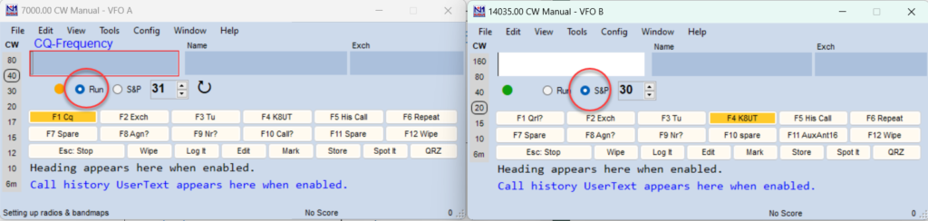
All of the Entry window features that are available to the single radio operator also work in SO2R/SO2V. For example, when tuning the band with the S&P VFO, spots that are in the bandmap are automatically inserted into the relevant call-frame (above the Call-sign textbox) when you tune across the frequency of the spot. Hitting the space bar (or Enter, in ESM) will pull the call-sign from the call-frame into the Call-sign textbox. Then if a station calls you on the run radio, toggling back and forth between Entry Windows with the \ key will keep the information in each Entry Window until the respective stations are logged.
The second Entry window will be opened when a call is clicked in the second bandmap, if it is not already open.
More SO2R info can be found in the SO2R section of the manual.
In SO2V (one radio – two VFOs = ‘normal’ operation) QSOs made on VFO-A have to be entered in the standard (first) Entry window. Making a QSO on VFO-B (transmitting and receiving on VFO-B) has to be done by using the second (VFO) Entry window. So when using both bandmaps, both Entry windows are needed to make QSOs on both VFOs. However, when operating split, the program transmits on VFO-A, and only the master Entry window needs to be open. If both are open in SO2V the second entry window displays the receive frequency
Call-sign Colors
There are two places where a call-sign can be shown in the Entry window , in the Call-sign field and in the Call-frame. The default colors for the call-sign text are consistent with other places throughout (such as the Band Panel and Available Mults and Qs windows), and are described below:
| Red | Single Multiplier Example: CQWW – qso is either zone or country multiplier (one multipliers) |
| Green | Double or better Multiplier Example: CQWW – qso is a zone and a country multiplier (two multipliers) |
| Blue | New contact |
| Gray | Dupe contact or an unworkable station in a non-workable country. This means that you don’t need this station because he is a dupe or you are not even ‘allowed’ to work him in this contest according the contest rules. |
Alternative colors may be used by specifying them in the Manage Skins, Colors and Fonts window, reached from the Config menu.
Other Features
- Clicking on the Exchange textbox will have the same effect as pressing Space when the cursor is in the call-sign textbox.
- The frequency, emission mode (e.g. CW, USB) and radio name are shown on the Entry window title bar.
- When tuning the band, if a station on the Bandmap is within the tuning tolerance, its call will be placed in the Entry window’s call-frame. When the call-sign textbox is empty, pressing the space bar will copy the call-sign from the call-frame to the call-sign textbox.
- Ctrl+P – Spot the station entered in the call-sign field to the active Telnet cluster, if any. You will be prompted for a comment. If no station is entered in the call-sign field, the last logged station this session will be spotted. Macros are accepted in the comment sen
- Alt+R – Toggles Repeat CQ. You can stop repeat CQing by beginning to enter a call-sign, or by hitting Escape. After you complete manual input, if you press F1, Repeat CQ will resume. Press Alt+R again to exit this mode.
- Ctrl+R sets the period of repeat in seconds or milliseconds.
- If repeat mode is on, a rewind symbol will be shown to the right of the cw speed indicator after F1 is pressed. This symbol is shown until the operator cancels the current cq by typing in the callsign textbox or by pressing Esc
- The repeat timer for CW and SSB is for the interval from when you stop sending CQ until CQ resumes.
- Repeat CQ is not available when using an external DVK, because there is no indication of when a message has ended.
- When using a radio with internal voice message memories, the repeat timer can be used together with a CAT macro in the relevant function key. Note: The repeat timer in this case starts when the radio command is sent to the radio. Users that use this function to trigger radio voice keyers must assign the radio command to abort the message to a separate function key, as Escape will not stop it.
- Ctrl+R sets the period of repeat in seconds or milliseconds.
- Ctrl+Shift+Fx – Record SSB message for the assigned function key. Pressing Ctrl+Shift+Fx again stops the recording. Fx can be F1 to F12, either Run or S&P mode.
- Ctrl+Alt+Fx – Record external DVK memory 1 to 4. Fx can be F1 to F4. An external DVK has to be connected and configured on an LPT port.
- Enter sends messages – An entire normal contact can be completed with the Enter key. More information is given in the Using Stored Messages chapter under ESM (Enter Sends Messages)
Ctrl+Q – enters Quick Edit mode. When you are in QuickEdit mode, the background of the Entry window textboxes are colored light blue. “QuickEdit” is also shown in the callframe.
- There is no check of the exchange against the contest rules, as is done when the QSO is entered normally. So check thoroughly what you change.
- If you have multiple filters or a crystal filter and DSP, Alt+’ (Alt+single quote) toggles between a wide and narrow filter for the selected mode (SSB, CW or Digital). This hot-key will work whether you have changed your filter codes or not. Filter codes can be set in the the bandmap right click menu.
- A warning message will be shown if user tunes away before logging a qso in the Entry window.
- Force logging – The program tries to help you by validating what you copy as the Exchange, but if it is balking and you don;’t want to stop to figure it out, you can force logging with Ctrl+Alt+Enter. A small Note window will pop up, pre-filled with the words “Forced QSO”. You can type over to remind yourself later what you copied, or simply hit Enter to log the default note.
Function Keys
General
Function keys F1-F12 are used for sending stored messages. The use of stored messages is covered in detail in another section. This section deals with the generic behavior of the Function keys.
The Function keys can be stacked. This means you can press several Function keys in close succession, and the contents will be sent in full in the selected order, with a space between. For example, you could press F4 to re-send your call (if you think the other station did not get it right) and immediately press F2 to send the exchange. The program will send the two messages seamlessly.
When hovering with the mouse over a Function key button the text to be sent is shown.
Run mode and S+P mode
If the Run radio button is selected, you will see the Run messages, and vice versa. Pressing Shift and a Function key sends the message stored in that key in the opposite mode (Run if S&P, and vice versa)
When you press Shift alone, the labels will change to those from the other mode (if different). This will help you decide if you want to send one of those messages by holding the Shift and pressing a Function key.
When you call CQ on a frequency, the marker CQ-Frequency is placed at that frequency on the Bandmap. Thereafter, if you are in S&P mode and you tune within the tuning tolerance of the marker, the program will switch automatically to Run mode. Clicking on the ‘CQ-frequency’ in the Bandmap also will place the program in Run mode again.
Note that when in Search and Pounce mode, you can switch to Run mode by pressing F1 to send what is called the S&P CQ message. That will send the S&P F1 message (for example, “QRL?”) and switch the program to Run mode.×
Normally when you are on your CQ-frequency you will be in Run mode and QSYing will switch to S&P mode. Press Alt+F11 to disable this automatic mode change, and again to re-enable it. A message in the Entry window status bar will indicate what the current state is. When on a DXpedition this behavior can be very useful.
Entry Window Menus
File Menu Selections
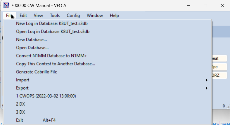
New log in database
Create a new contest log in the current database. More info here.
Open log in database
Open an existing log in the current database. More info here.
New Database
Create a new log database. Change the proposed name (ham.s3db) into a meaningful name for the use or contents of this new database. Until you change to another database (see Open Database below), this database will be opened by default at startup of the program.
Open Database
Open an existing log database. Select from databases already created.
Convert N1MM Database to N1MM+
This option is intended for use after you install N1MM+ but before you delete NLClassic from your computer. Because N1MM+ uses SQLite, in order to access an old database (.mdb file) you need to do two things. First, open the old database in NLClassic (any version 14.0.0 or after – if your only copy of NLClassic is older than 14.0.0, you can find an updated version on the web site at >Downloads >Program Files >Archive files (classic version). Then close it, close N1MM Classic and open N1MM+, select Convert…(this option) in NL+, and navigate to your N1MM Classic program directory. Select the database you want to convert, and hit Open. You will be asked for the name you want to give it under N1MM+, and when you hit Enter the database will be converted and placed in the [user]\My Documents\N1MM Logger+\Databases subfolder.
Copy This Contest to Another Database
Copy the current contest log to another database. If the target database does not exist, you should create it first, using the New Database command. The original database is not changed, nor does the program start using the new database unless Open Database is subsequently used to open it.×
There are many reasons why you might want to copy contests from one database to another. Many users have created databases organized by year, by contest type, and so on. This option makes that easy. Some users, particularly those whose CPU or PC memory capacity is limited, have found that they get improved program performance by using a database that has only one contest (or relatively few QSOs) in it. If you start off using a database with many contests already in it, you can always create a new database and then copy the QSOs you have already made to it.
Generate Cabrillo File
Invites you to name your Cabrillo file for the current contest, double-checks your sent exchange, creates the file, and opens it in Notepad for you to check before you send it in.
Once created, the Cabrillo file can be edited using Notepad or any text editor. Make sure that the Station information (Config > Change Your Station Data) and Contest Setup (File > Open Log in Database) are correct before creating this file. Be sure to enter the correct Sent Exchange in the Contest Setup dialog, or else your Cabrillo file will be wrong.
Double-check your entry class before generating the Cabrillo file. The defaults may well not be appropriate for your entry in this particular contest. The program defaults to Single Op Assisted as your class, and you may not want that. For Multi-op stations select the correct Operator Category in the Contest Setup window. This generates the correct numbers for each station; in Multi-single, the station number field (the last digit in each line) identifies the Mult and Run station.
It is a good idea to rescore the contest (Tools>Rescore Current Contest) before submitting and check to be sure that the header of the Cabrillo file is correct before submitting the log. Some contest organizers use non-standard operator categories (i.e. not in the official Cabrillo specification); in these contests you will have to edit the category by hand to make it agree with the organizer’s requirements.
Note that if your radio was not interfaced to the program when contacts were logged, those contacts will be exported with bottom-of-band frequencies (e.g. 14000), whereas if you used an interfaced radio, the exact frequencies will be exported in the Cabrillo file.×
Note: The Cabrillo standard only supports one mode designator for digital modes: RY. In some digital or mixed-mode contests, PSK and RTTY may be considered separate modes, and the contest organizers may specify additional non-standard designators such as PK. The Logger’s Cabrillo mode export string for PSK is “PK” unless the contest considers RTTY and PSK to be a single digital mode. When this occurs the mode export string is “RY”. Because the use of these mode designators is non-standard, you should always check with the organizer’s file specification and if necessary, edit the Cabrillo file to meet the organizer’s requirements.
Import
Import ADIF from File
=**Import ADIF from file… – Load the data from an ADIF file into the current database. The Contest Name in the ADIF file must match the contest name in the current database.
A single N1MM Logger+ log database cannot contain QSO’s with identical time stamps (time and date). If the contacts contained in the ADIF already exist in the current database, YOU MUST open a new database and contest before importing the ADIF file.
If the ADIF file contains tags that are not used by the N1MM Logger+ program, they are ignored. This is often the case when the ADIF file is generated by a different program. To view the N1MM Logger+ ADIF tags open a contest of the same type, log one or more dummy QSO(s), then export the ADIF file. Compare the Contest Name and QSO tags for the important QSO elements. Note that ADIF files for WAE contest logs do not contain QTCs, only QSOs, and therefore you cannot transfer WAE logs including QTCs between databases using ADIF files. See the FAQ for more information.
The imported contacts are not scored during the import process. It is necessary to do a rescore (Tools > Rescore Current Contest) after the import in order to have the points and multiplier status of the newly imported contacts recorded and included in the calculated contest score.
Import Call History
- Import Call History… – Call history files (typically with the extension .ch or .txt) are used to suggest exchange elements based on past experience with the current station. See this full explanation
- Import State and Province Abbreviations… – Import the state and province abbreviations used in many contest modules. This is done automatically when changing databases, but may be worth trying if you have trouble in a contest (particularly a QSO Party) with the program not recognizing certain county, state or province abbreviations. Do a rescore after executing this menu item, when QSOs have already been logged.
Import QSOs from a Transaction (TRN) Log File
- Recover QSOs from a Transaction Log… – Import the created transaction log (also known as a transaction file). This file is created automatically and stored in the Databases\TransactionLogFiles sub-directory within the N1MM Logger+ User files area and have the filename suffix TRN. These files are used as follows: During normal operation N1MM Logger+ saves the information about each QSO in a simple text file. These files are stored in a sub-folder of the user Databases folder, normally C:\Users\
\Documents\N1MM Logger+\Databases\TransactionLogFiles and can be used to recover in the event the database file is corrupted. Here’s an explanation of how you can use those files to recover your data quickly, during a contest, or at your leisure later: - The transaction log is created for each contest you log to
- The file is closed after each transaction and reopened to force the data to be written to disk
- To keep things simple and foolproof, you are not allowed to change the name of the transaction log
- The name is used to make sure you are loading it properly, and to prevent mixing logs of two contests. Example name: ‘CQWWCW – 2005-09-19 – 14.TRN’ i.e.: Contest name – date log created – an internal index number
- To Recover your log, you MUST import the transaction log into a NEW (empty) database and a NEW contest log. See this link.
- The new contest log must be the same contest type as the contest from the transaction file (Example: if restoring CQWPXCW, the new contest must also be CQWPXCW)
- As you load the transaction log, a new transaction log is automatically made with the transactions in the first log. Thus you should never have to merge logs. You always use the last one
Export
Whenever the “Save File” window prompts for a filename, the default is your call-sign.txt (the callsign as entered in the Configurer >Station Information dialog). “/” and some other common characters are not accepted by Windows, so if your contest call sign was N1MM/P, use something like “N1MM_P.txt” instead.
ADIF Export Sub-menu
- Export ADIF to file… – Create an ADIF file. This file can be used to export the current contest, for import into a logging program or another contest program (horrors!). Deleted QSOs are not exported; select the ‘DELETEDQS’ contest to export these.
Note: QTCs in WAE contest logs are not exported in ADIF files, because there is no provision for QTCs in the ADIF specification.
- Export ADIF to file by date… – Create an ADIF file from the currently-selected contest, starting from the date set. The first time you use this function the default date will be 1900-01-01 (yyyy-mm-dd). The second time the suggested date and time will be the last time you exported with this option. You can always over-write the date/time if you want. This function is especially useful when you want to export into a (general) logging program to do award tracking etc.
Deleted QSOs are not exported; select the ‘DELETEDQS’ contest to export these.
- Export ADIF to file by date from ALL contests… – Create an ADIF file from all QSOs in all contests starting from the date set. The first time you use this function the default date will be 1900-01-01 (yyyy-mm-dd). The second time the suggested date and time will be the last time you exported with this option. You can always over-write the date/time if you want. This function is especially useful when you want to export into a (general) logging program to do award tracking etc.
×
When a contest exchange uses a ADIF field that is not included in N1MM+’s contest database, the N1MM+ ADIF Export will define that exchange with an ADIF custom tag like <APP_N1MM_EXCHANGE1:2>1D. To import into a general logging program that is expecting standard ADIF tags, you will need to use a text editor with Global Search & Replace to change the custom tag to a standard tag. For example, in Field Day, ADIF exports the CLASS exchange as <APP_N1MM_EXCHANGE1:2>1D. You would need to globally replace all “APP_N1MM_EXCHANGE1” with “CLASS” for a successful import.
Deleted QSOs are not exported; select the ‘DELETEDQS’ contest to export these.
- Export ADIF to file by Multi-User Station Name – Create an ADIF file from all QSOs from one station in a Multi User environment when you are currently logging DX. Otherwise, it exports only from the contest you are logging in. A station name has to be supplied from the Network Status window, after which you will be asked for a filename.
Note: When using ADIF export and the contest name contains “RTTY” or “JARTS” the export mode is set to “RTTY” even when the log file shows otherwise (i.e. LSB).
- Export to File (Generic)
- Export to File (Generic), order by QSO Time (normal)… – Creates a generic file named call-sign.txt from the contest log ordered by time (and not by band). In some cases this will be the file requested by the contest manager. This file can also be used to import into a spreadsheet or database program, or your logging program if it can’t import ADIF format. The exported file can be edited with a text editor like Notepad.
- Export to File (Generic), order by Band… – Creates a generic file named call-sign.txt from the contest log ordered by band, per band ordered by time. In some cases this is the file requested by the contest manager, for example in VHF and up contests.
- Export EDI to file by band… – Create an EDI (REG1TEST) file. This is a regular file format used for VHF contests in Europe. A separate file will be created for each band with QSOs made on it.
- Print Score Summary to File… – Print the contents of the Score Summary window to a text file with the default name call-sign.SUM Example: N1MM.SUM. This can also be done by right-clicking the Score Summary window.
- Export Call History… – Exports the information in the Call History database table. This table can only be filled or revised by using Import Call History. Do your editing on the Call History text file before import.
- Export Function Keys to file – Export the contents of the function keys to file (*.mc). Exported function key definitions can be imported using the Function Key Editor
- SSB Function Keys… – Export the SSB function keys.
- CW Function Keys… – Export the CW function keys.
- Digital Function Keys… – Export the Digital function keys (the Entry window keys, not the extra keys from the Digital Interface).
Contest List
At the bottom of the File Menu is a list of the last 9 contests you have had open, along with the databases they are contained in. This provides a very convenient way to switch between contests when you want to participate in more than one simultaneously. You can open the File menu and use your mouse to select the contest you want to work next, or you can hit Alt+F, which opens the File menu, and then hit the number (1-9) corresponding with the contest you want.
The contest you currently have open will always be numbered “1”, and the next previous will be numbered “2”, so if you want to toggle between just two contests, all you need to do is set them up and then Hit Alt+F, then 2, to jump back and forth.
Edit Menu Selections
- Wipe Out Entry Fields Ctrl+W – Clear information from the current contact (equal to Alt+W).
- Edit Last Contact Ctrl+Y – Open a dialog to allow all fields for the last contact in the log to be modified.
- Add a Note to Last/Current Contact Ctrl+N – Add a note to the current contact in the Entry window, or the last QSO logged when no call-sign is shown in the Entry window.
- Edit Current Contact – Open a dialog to allow all fields for the current contact (still in the Entry window) to be modified. Double clicking in the Log window on a field with user-supplied data will open in-line editing of that particular item. See the Log Window below for more details on this.
- Quick Edit – Quickly edit QSOs already in the log. If the text boxes in the Entry window are colored blue, you are in Quick Edit mode. Quick Edit (Ctrl+Q) always starts with the last QSO in the log. The call-sign and any exchange elements are displayed in the Entry window, with the legend “QuickEdit” in the call-frame. Correct any errors and hit Enter, or hit Esc to exit quick Edit mode. Once you are in Quick Edit mode, hitting Ctrl+A moves forward one QSO, while hitting Ctrl+Q moves backward (in time) one QSO.
- Quick Edit Previous Contacts (Forward) Ctrl+A– Quickly edit the QSOs worked before in the log. Ctrl+Q moves back one QSO, Ctrl+A moves forward one QSO.
- Increase Received NR by 1 Ctrl+U – Increase the number in the exchange field by 1. You will find this useful during serial number contests when you are in a pileup and you need to keep incrementing the DX station’s serial number because you can’t get him in the log…
- Find/Find Again Ctrl+F – Find the call-sign entered in the call-sign field in the log. Pressing Ctrl+F again will find the next instance.
View Menu Selections
- Max Rates – Shows the best 1-minute, 10-minute and 60-minute rates achieved in the current contest. File > Copy these messages to the Clipboard is self-explanatory, and appears for all of the View functions below..
- Off Times – Shows off times. Lists each off period that complies with the contest rules, or each off-time of 30 minutes or more if the contest rules do not specify. Each off period shows when it began and ended, and the duration. Total on and off time is also given. Time between the start of the contest and the first logged QSO is counted as off time, as is time between the last QSO and the end of the contest.
- Runs – Shows all runs. The program counts consecutive QSOs in run mode until an S&P QSO or band change. Off times do not break a run if you resume in Run mode on the same band.
- Notes – displays all contacts with notes.
- Statistics – Show statistics for the selected contest. Many choices available. See the Statistics Window section.
All greyed-out ‘Show’ items below become active when valid call-sign information is entered in the call-sign textbox or the call-frame. Some formats may not be compatible with all current cluster command sets
- Show Last 10 Spots – Show the last 10 DX cluster spots for the call in the call-sign field or call-frame. Telnet cluster connection required. Format may not be compatible with some cluster nodes.
- Show Station – Show the station information for the call in the call-sign field or call-frame. Telnet cluster connection required
- Show QSL/Telnet – Show the QSL information for the call in the call-sign field or call-frame. Telnet cluster connection required.
- Show Sunrise/Sunset – Show the Sunrise/Sunset information for the call in the call-sign field or call-frame. Telnet cluster connection required.
- SH/DX Current Call or Spot – Shows DX information from the current call in the call-sign field or spot. Telnet cluster connection required.
- Show QRZ (Internet) – Show the information that QRZ.com has for this call using your browser. An Internet connection is required. present.
- Show Google (Internet) – Show the information that Google.com has for this call using your browser. An Internet connection is required.
- Show ? on Unmatched Calls – When the Check window is open and a call-sign is entered in the call-sign textbox, a “?” will appear following the call-sign if no matching call-sign was found in the Check window’s sources. Uncheck the option if you do not wish this to happen.
Tools Menu Selections
- Rescore Current Contest – Rescores the current contest. This is required before submitting a log if anything has changed, such as a cty.dat or .sec file, or if you have edited or imported any QSOs. It rechecks QSO points and multipliers and makes any corrections needed
- Rescore last N Hours – Rescores the last N hours for the current contest. It may be run at any time but is rather slow.
- Download and Install Latest Check Partial file (Master.scp)(Internet) – Opens your web browser to download the latest version of the check partial file. Select the file to download and save it in the Support Files subfolder of the N1MM Logger+ folder, under [user]\My Documents.
- Toggle Tune (CW mode) Ctrl+T – Switches the radio into CW mode and using the CW keying interface, keys the transmitter. PTT is asserted. To stop tuning, press the Esc key or Ctrl+T again. After tuning ends and PTT is released, the radio returns to the original mode.
- __Download latest N1MM Logger+ pdf manual (Internet)
- Download and install latest country file (wl_cty.dat)(Internet) – Downloads and installs the latest wl_cty.dat file in the correct location (Internet connection required).
- Import country list from downloaded file (Internet) – This option is retained for contests that use a non-standard cty.dat file that is not on the standard country file website.
- Add call to country – Specify a country for the call-sign in the call-sign textbox in the Entry window. If no call-sign is entered this menu item will be grayed out. This is a quick way during the heat of a contest to add a country temporarily, until the next time you import wl_cty.dat. Making changes permanent requires editing the country file (wl_cty.dat) to be imported.
- Tune to beacon for this band (20-10M) – This will change the radio’s mode to CW and tune to the NCDXF beacon on the current band, if that band is 20, 15 or 10 meters. The station currently transmitting and the power steps are displayed in the status bar of the Entry window that has the Entry focus (green LED). Short Path and Long Path bearings to the beacon are shown. See this website for current information on the beacon program.
- Update Call History with Current Log – Update the current call history table in the Admin database with the QSOs from the current log file. Information associated with a call-sign will be added, or updated if already in the call history table. For VHF contest, in particular, where two Maidenhead grid fields are provided, the behavior is a bit different. When both grid fields are filled and a new, third grid has been logged, the oldest grid will be removed, and replaced by the grid from the first field. The new grid will be added in the first position. The same change in position will happen when only the first grid field is filled and a new grid is added from the log. A 4-digit grid will be overwritten by a 6-digit grid when the first 4 characters are the same, adding precision to the entry.
- Clear Call History then Update with Current Log – As above, except clears the call history table before adding contacts from the current log. Can be used to start a new call history file.
×
Saving an Updated Call History file
After you have done this, the modified Call History table is only in the Admin database. To get it into a Call History text file, you must export the table to a file. Do this on the File menu, under Export>Export Call history.
If you want to have a specific Call History Lookup file loaded and enabled whenever you start that contest, you need to add the short contest name (the one in the Contest Setup dialog) to the Call History text file as a comment (preceded by a “#”. You can even have it loaded and used for more than one contest, by putting in multiple contest names. Example (omit the quotation marks):
“#NAQPCW”
“#NAQPSSB”
For QSO parties, the state abbreviation is required after the contest name. Example:”#QSOParty PA”
- Turn Rotor Alt+J – Turn rotor to bearing for the call-sign in the Entry window or to the call-sign in the callframe (when call-sign field is empty).
- Alt+L will turn the beam to the proper bearing for long path
- Stop Rotor Ctrl+Alt+J – Stop turning the rotator.
- Telnet Window Tools – Opens the Filters tab of the Packet Window.
- Program Execution Logging (Diagnostics folder) – There are several different logging options, all of which export to the Diagnostics folder, and may prove useful to the developers in tracking down performance and other problems. We recommend that you click Disable All on the sub-menu unless you are encountering serious delays or other execution anomalies.
- Save Window Positions – Save the current window positions to the .ini file.
- Window positions are automatically saved when the program is closed.
- Window positions are saved per operator. Use Ctrl+O to enter the call of the operator, and click ”Save Window Positions’. The next time that operator signs on (using Ctrl+O), the window setup will be adjusted to the saved layout.
- Restore Window Positions – Restore from the .ini file the most recent saved window positions. The screen will update immediately
- Window positions are restored per operator (when saved first by the operator). Use Ctrl+O to select Operator and press ‘Restore Window Positions’. The windows will change to their new positions immediately. This enables easy reconfiguration of the screen when changing operators at a multi-op.
- Check for New Program Version and Install – Useful if you have elected not to install a new version when the chance was automatically offered, and now want to remedy your “grievous error.”
Note –More info about rotator control can be found in the Supported Hardware section of the Interfacing chapter.
Config Menu Selections
Many of the selections after the Configurer can also be invoked in other ways, such as hot-keys or from other windows.
Configure Ports, Mode Control, Audio, Other – Also called the Configurer.
This a very important dialog which determines many aspects of the program’s external interfaces and operation. Go here for detailed documentation of this dialog.
Change Your Station Data
Modify overall Station information – name, call, address, state, latitude, longitude, etc. The call-sign and location information entered here is very important for most contests, It determines what country, state or province you are in, which may in turn affect the required exchange, scoring, which stations may be worked for contest credit, etc.
Logger+ Audio Setup
This menu item only appears when the following menu item has been checked. For users with Windows Vista or later operating systems, this is where you set up your audio options for the new Logger+ Audio functions, including playback and on-the-fly recording of stored voice messages. If you are running Windows XP, you will not see this option. If you check the next option below, Use Logger+ Audio, then the Audio tab will not be present the next time you open the Configurer.
The Monitor tab
This tab opens whenever you open the Logger+ Audio Setup
The left-hand slider (“Set”) sets the output level going to your radio. You will want to set this so that your radio indicates the correct microphone level and amount of compression. When playing a .wav file, the narrow “Wav” bar-graph displays the relative level of the peaks of the recording being played. The wide “Output” bargraph displays the peaks of the output going to your radio. The two are independent; if the Wav file bargraph shows relatively low peaks, you may want to re-record it to improve the signal-to-noise ratio.
The right-hand slider sets the record level for “on-the-fly” recording, and the narrow bargraph just to its right displays the relative sound level that is being recorded.
When you close N1MM+, the soundcard(s) output level(s) and microphone input(s) levels are returned to the previous settings.
The “Test” button will play a pre-recorded message, so that you can test your playback setup without having to record something first.
The lower pane of this tab reports each stored message that is sent, which can be helpful for debugging.
The Playback tab
In the first options box, the first choice uses a single soundcard for SO1V/SO2V. The other 3 are all for SO2R – Single Soundcard Mono (where an external controller is used to route the audio between radios), SO2R Single Soundcard L/R (using one channel for each radio), and SO2R Two Soundcards Mono, where each soundcard is connected to one radio.
In the second options box, select the Playback device that will feed audio to your radio. The set of possibilities displayed is dependent on your specific computer configuration.
A growing number of radios have internal “sound cards”, called CODECS. If you have one of these and wish to use it as the sound card for that radio, check the box. Of course, you cannot use a single radio CODEC for more than its own radios, so the first option needs to be set to match.
The lower pane of this tab shows interactions between N1MM+ and windows audio functions.
The Message Recording Tab
This tab will vary with your choices on the Playback tab. If you choose two-soundcard SO2R you will need to choose inputs for each card to enable on-the-fly re-recording of stored messages
The Sample Rate options are 8000 and 12000, and are set here for on-the-fly recording only.
The lower pane will report the beginning and end of each on-the-fly recording event.
Your microphone will be muted during playback if you check that option.
Use Logger+ Audio
Activates the audio setup in the selection just above, and deactivates the audio tab in the Configurer, if your PC is running Windows 7 or later. If you are running Windows XP, neither this option nor the configuration menu above will appear on your screen.
Enter Sends Message (ESM mode)
Ctrl+M toggles this mode on and off – first introduced by N6TR in TRLog, and much improved in N1MM Logger. The program anticipates the needed sequence of messages to complete a QSO in either Run or Search & Pounce mode, and sends each one in turn by simply hitting Enter. See ESM for further details.
Spot all S&P QSOs
Spot the contact when you log it. This option is turned off by default when starting the program, to avoid spotting everything you work unless you want to.
If this option is checked, a contact is automatically spotted when:
- You complete the QSO in S&P mode and
- the spot is not already on your Bandmap at the same frequency (+/- the tuning tolerance)
The Spot Comment tab on the Telnet window allows the user to specify a comment for spots, including elements of the log entry for the spotted call, such as Zone or Exchange.
QSYing wipes the call & spots QSO in bandmap
Very useful for S&P. If you enter a station’s call in the Entry window, and then tune off for any reason (he doesn’t answer your call, or…) the call is shown bold in the bandmap. These ‘spots’ are not sent out on Telnet. The setting of this feature remains as it was across program restarts.
All bandmap features work on these ‘spotted’ stations so they are easy accessible if needed. Self-spotted stations are easily recognized because they are shown in bold.
This option is also available on the Filters tab of the Telnet window.
Grab Focus From Other Apps When Radio Is Tuned
Brings N1MM+ to the front over any other app when you tune a radio that is interfaced with the program.
Do not automatically switch to Run on CQ-frequency
When selected and you QSY back to an old Run frequency, the mode stays in S&P. F1 and Alt+Q continue to switch to Run mode. This is most useful in Sprint-like contests, where you QSY frequently and want to avoid unexpected switches to Run mode
Show Non-workable Spots and Dupes in Bandmap
This option is also found on the Filters tab of the Telnet window. When checked, this option displays all previously worked (dupe) call-signs, as well as stations that don’t count in the current contest, in grey on the bandmap. When navigating the bandmap with hot-keys (Ctrl+Up/Dn, for example), grey calls are ignored. Its use is highly recommended to avoid wasting time on non-workable stations when S&P, even if operating unassisted.
Reset Rx freq to TX when QSO is logged (RUN and split)
When using the main VFO to transmit and the other to receive (split mode) after each logged QSO the RX frequency will be made equal to the TX (main VFO) frequency. It resets after every RUNNING QSO. Using a radio with VFOs A and B, this feature is there to let you use the main frequency control as an RIT. With Main/Sub radios like the Icom 756/7800 series you can not RX on SUB without receiving on both VFOs. In this case put RX on Main and TX on SUB for Alt+S to work.
Sub Receiver Always On
Yaesu FT-1000 series, Icom IC-756 series, IC-781, IC-775, IC-7800, Elecraft K3 with subRX only: Selects the mode for Dual Receive toggle (Alt+F12).
- When selected –
- Yaesu FT-1000 series: The sub receiver will be left on (blinking green RX led)
- Icom IC-756 series, IC-781, IC-775 and IC-7800 only: Dual watch is not turned off when you switch from SUB to Main with Ctrl+Left Arrow or PAUSE
- Elecraft K3: The sub receiver will be left on
- Not selected – The sub receiver will switched off (RX led off)
CQ Repeat – Alt+R
Toggle for repeat CQing. With Winkeyer, beginning to enter a call-sign in the Entry Window terminates the CQ, but the program remains in CQ repeat mode. The function is automatically turned off when no longer on the CQ-frequency and the mode changed to S&P.
Set CQ repeat time – Ctrl+R
Specify the repeat interval (CW or SSB with sound card) in seconds. The default value is 1.8 seconds.
CW / PH AutoSend Threshold – Ctrl+Shift+M
Start sending the call-sign after a certain number of characters typed AFTER the last number in the call-sign. The minimum threshold is 1. 0 will turn off the feature. Only works when in RUN mode, not in S&P. More info in the Logging Key Assignments section.
Enable Call History Lookup
When enabled, Call History Lookup can be used to pre-fill the exchange during a contest to save typing, or to display user comments or notes for specific call-signs. Reverse Call History Lookup uses the same Call History file to find stations whose exchanges fit what you have entered in the Exchange field. It is enabled by the same Config menu entry. Follow the links above for the full story.
Change CW/SSB/Digital Message Buttons – Alt+K
Change the contents of the CW/SSB/Digital Function Key messages). The maximum length of text in each CW, SSB and RTTY button is 255 characters. Alt+K will access the relevant list of definitions, depending on the mode you are in, or you can right-click in the button area to get there. See the discussion of the Function Key Editor here.
- Change CW Function Key Definitions – Change the contents of the CW messages.
- Change SSB Function Key Definitions – Change the contents of the SSB messages (.wav files).
- Change Digital Function Key Definitions – Change the contents of the Digital messages.
Change Band Plan
Band plans play important roles in a number of places in the program. They can affect the mode contacts are logged in, the mode that is assigned to incoming Telnet spots, and whether or not those spots are displayed in the Bandmap and Available Mults & Qs window. The usage of modes in some frequency segments depends on the contest. For example, frequencies in the 7040-7070 kHz segment of 40 meters might be used for SSB (DX stations operating split in a DX phone contest), digital modes (in a RTTY DX contest), or for CW (in a CW contest or a domestic North American contest). There is no one size fits all setting, and even for a single operator the choice of where to place the sub band limits can depend on the contest. Therefore it is important to be able to adjust the band plan. This section describes one method; alternatively, there is a graphically-based method that can be used from the Bandmap window.
The sub-menu offers the choice of CW or digital bandplan tables which can be edited and saved. You can only designate one CW and one digital band segment per band.
By definition, digital segments override cw segments, and both override SSB segments. That means that unless a band segment is designated for CW or digital modes, it will be shown as SSB.
For example, on 40 meters, you can enter a CW segment of 7000-7100 KHz, and a digital segment of 7040-7050. The resulting bandmap markings will look like this:
Changes in Band Plan Management
N1MM Logger+ has adopted a new approach to designating and displaying CW, digital and SSB band plans. You can now adjust the sub-bands that are displayed for any individual band through right-clicking on frequency labels (e.g. “7045”) in the relevant Bandmap. See this link for details.
Manage Skins, Colors and Fonts
See the Skins, Colors and Fonts Window.
Change Operator Call-sign Stored in Log (Ctrl+O)
This function is used mostly in multi-operator situations, to change the operator callsign stored in the log and to call up a preferred window configuration when a new operator takes over.
Change Exchange Abbreviations
The idea here is to hedge against having people send you abbreviations during contest that are not the same as those recognized by the contest organizers. We’ve all had people send us “ALA” when they meant “AL” or ALTA when they meant “AB”. The problem is particularly bad in QSO parties. Put the non-standard abbreviation in the “Abbreviation” column, with the correct one in the Section Column. Click on the Section heading to sort by the standard abbreviation, so you can see various alternatives that you have entered.
SO2R
Much more info about Single Operator Two Radio operation of the program can be found in the SO2R chapter.
- Dueling CQ’s – Ctrl+B – SO2R feature that alternates sending CQ on each radio in turn, listening on one while transmitting on the other. Supported for both CW and SSB.
- Changing either radio in frequency more than 200 Hz will terminate Dueling CQ.
- Set Dueling CQ Repeat Time – Adjusts time after CQ ends on one radio before it starts on the other. In seconds.
- Focus on Other Radio – Ctrl+Shift+K – FocusOther
- FocusOther Always Swap – Focus always switches to the other radio when one radio is transmitting, and always switches back to the original radio when transmission is completed.
- Toggle CTRLFx Macro – Ctrl+Shift+L – When enabled and present in one of the function key definitions, the {CTRLFx} macro executes Fx (Function key definition x) on the opposite radio. An example is TU{CTRLF1} in Radio 2’s F3 slot, which sends TU and then sends the other radio’s F1, used to get quickly back to the Run radio and call CQ after finishing an S&P QSO on Radio 2.
- Two Keyboards – Enables the use of two keyboards, one for each Entry window. Plug in two keyboards before starting N1MM Logger+. The first keyboard you type in after starting the program will control the left (Radio 1) Entry Window. The other keyboard will control the right (Radio 2) Entry Window. The pause key is disabled, since you no longer need to be able to switch Entry windows from a single keyboard. The \ key moves keyboard focus to the Entry Window associated with that keyboard without actually sending any keyboard commands to that window. Note that the use of keyboard remapping software, such as AutoHotKey, may not work correctly with two keyboard operation.
- TX Lockout (Digital) – Select a lockout option. Also MIXED mode category is supported i.e. blocks second TRX on the same band and mode. This doesn’t prevent RX overload. For digital modes only
×
There’s No Substitute for A Hardware Lockout
Software lockouts are inherently less reliable than hardware systems, because of the vagaries of networking, RFI, etc. We urge you not to rely solely on software lockouts to prevent rule violations or hardware damage.
- Multi-TX – This is the default setting. Start CQ on radio A, next a CQ on radio B, both are active. (no lockout)
- First one wins – Start CQ on radio A, pause, Start CQ on radio B. The radio B CQ is ignored since radio A is already active, so if you press a F-key for the second radio while radio1 is transmitting, the radio B F-key is ignored.
- Last one wins – Start CQ on radio A (CQ starts), pause, Start CQ on radio B. The CQ on radio A will aborted and the CQ on radio B will start so if you press a F-key for the second radio while radio A is transmitting, the radio A transmission is interrupted and radio B transmits.
WAE – Special commands for the WAE DX contest only
- Toggle WAE QTC mode – Ctrl+Z – Toggle the WAE QTC mode between QSO and sending/receiving QTCs. See WAE contest setup instructions.
- WAE Received QTC Confirmation – Can be used to enter the WAE confirmation string or .WAV file (CW/SSB only). See the Open QTC Window Setup Area menu item for more comprehensive QTC setup options
- Max QTC Number for callsign colors in Band Map – opens a dialog box to allow you to set the number of QTCs to be used for displaying the special colors in the bandmap for stations with QTCs remaining
- Ctrl-Z sends QTC? automatically (EU stations, Run mode only) – When this option is checked, pressing Ctrl+Z while in Run mode automatically sends QTC? and puts the program into QTC mode (CW only, EU stations only).
- Open QTC Window Setup Area – Opens a dialog window in which you can change various settings for QTCs. This window has three tabs, one for CW, one for SSB and one for RTTY.
- CW Setup – checkboxes for a series of options applicable to EU stations receiving QTCs, plus a box where you can customize the TU message on exit. Check any of the check boxes that you wish to activate; if the option is not checked, the default action will be selected.
- In CW when moving out of Serial QTC window Send CFM String and move to next line bypassing CFM button.
- In CW when moving from QTC header send QRV string and move to first QTC entry line.
- In CW pressing Hdr Agn clears the QTC Header Window.
- In CW pressing Agn clears all QTC textboxes for that row.
- TU message to send on Exit – Can be used by either EU or non-EU stations to set the message to send at the end of a block of QTCs. The {QTC} macro may be used to send the QTC block number from the header in the TU message. If the TU message is left at the default (“Not Set”), the normal F3 TU message will be sent when exiting the QTC window
- SSB Setup – selection boxes containing the locations of wav files the program will look for wav files to be used for QRV, Confirm, Again? and TU voice keyer messages by EU stations receiving QTCs. The Logger+ audio method must be used, i.e. these files will not work if the legacy audio method from Logger Classic is used. There are three boxes to the right of each path name. The first one is green or red depending on whether the file was found or not. The second box is a button labelled R, which you can use to start recording. The R will change to S while recording is active; click on the S to terminate recording. The third box is a button labelled P; press this button to play the wav file (for testing).
- RTTY Setup – boxes containing the messages that will be sent during the QTC process by both receiving (RQTC) and sending (SQTC) stations. Note that you do not need {TX} and {RX} macros in these messages
- RQTC Messages:
- RX Ready
- All Agn
- Agn – the $ macro is used in this message to send the number of the QTC whose Agn? button (in the RQTC window) was pressed
- Save QTC – the message to send when the QTCs have all been received and recorded
- SQTC Messages:
- RU QRV
- Send All Heading – the {QTC} macro is used in this message to send the header number, e.g. 26/10
- Send All Ending – message to send after the block of QTCs has been sent
- Save QTC – message to send after the QTCs have been acknowledged
- QTC Spacing – normally {ENTER}, but some users may need {ENTERLF}
- Default Number of QTCs to Send – sets the maximum number of QTCs that will be sent in a QTC package (normally 10)
- RQTC Messages:
- CW Setup – checkboxes for a series of options applicable to EU stations receiving QTCs, plus a box where you can customize the TU message on exit. Check any of the check boxes that you wish to activate; if the option is not checked, the default action will be selected.
Clear INI file settings
Option to clear out the ‘N1MM logger.ini’ file. Generally, it will be preferable to rename the existing .ini file to something like N1MM Logger.old, so that you can retrieve your settings if you need them to re-configure.
SO2V Dual Receive
- Repeating CQ Ends With VFOB Window Entry – When this option is selected, after every CQ sent from VFO A using the Auto CQ Repeat function, the keyboard focus is automatically shifted to the VFO B Entry window. If someone responds to your CQ, you will need to press the \ key before starting the QSO, but if no-one responds, the keyboard focus is in the VFO B Entry window to allow you to make an S&P QSO there.
Window Menu Selections
- Available Mult’s and Q’s – Display the Available Mult’s and Q’s window. More info in the Available Mults and Qs Window chapter
- Bandmap – Display the Bandmap window. In SO2R/SO2V each Entry window has its own Bandmap window. More info in the Bandmap Window chapter
- Check – Display the Check window. More info in the Check Partial Window chapter
- CW Key Ctrl+K – Display the CW Key window. Pressing Ctrl+K again or Enter will close the window but will continue sending the message. Pressing Escape will stop sending the message. The windows is multiline (for pasting in text) and can be resized. The font type and size is the same as used in the Entry Window
- CW Reader – Display the CW Reader window.
- Digital Interface – Display the Digital Interface window – see the Digital Modes chapter
- Entry Window – Displays the Entry window
- Gray Line – Opens the Grayline window. More info in the Grayline Window chapter.
- Info – Display the Info window. More info in the Info Window chapter
- Log Ctrl+L – Display the Log window (toggles between open and minimized). More info in the Log Window chapter
- Move Multipliers – Display the Move Multipliers window. For every call sign in the spot table and every band/mode selected using the Select Band & Mode button, displays the multiplier status of that call sign and indicates with background shading which band that station was spotted on. The multiplier status depends on the program’s ability to determine the multiplier status solely from the spot information. It is not updated when a contact is logged, deleted, or spotted, but only when the Refresh button is used. A left-click on a call sign will QSY the radio to the first spotted band. If a station is spotted multiple times, repeated clicks will QSY to the next spot on the line. In SO2R or SO2V, if a radio or VFO is already on the spot band, that radio/VFO will be used, otherwise the active focus radio will be used, or Shift+Click will QSY the other radio. A mouse wheel click will delete the line.
- Multipliers – Click to display the Multipliers sub-menu
- Countries – Country multipliers are displayed
- Grid Squares – Grid square multipliers are displayed
- Sections/states – Section or state multipliers are displayed
- Zones – Zone multipliers are displayed
- County/Other – County multipliers (or other multipliers in some contests) are displayed
- Network Status – Display the network status window – see the Network Status Window chapter
- Rotor Windows – Opens the rotor windows (only if rotor windows are selected to be displayed in the Configurer under the Antennas tab) – see the Rotator Control chapter
- Talk to Another Station Ctrl+E – If networking is enabled, opens the network Talk window – see the Network Status Window chapter
- Score Summary – Display the score summary window. More info in the Score Summary Window chapter
- Telnet – Display the Telnet window. More info in the Telnet Window chapter
- Visible Dupesheet – Display the Visible Dupesheet window. More info in the Visual Dupesheet Window chapter
Ctrl+Tab can be used to rotate focus among open windows in a round-robin fashion.
Ctrl+Shift while clicking on the name of an already opened window will move it to to the upper left corner of the screen. This is useful for windows that have been lost.
Help Menu Selections
- EntryWindow Specific Help – Shows the Entry Window sub-section of the Windows chapter of the Digging Deeper section of the on-line manual. Requires an active Internet connection
- Manual Index – Shows the full index of the on-line manual. Requires an active Internet connection
- Supported Contests & Setup – Shows the Supported Contests chapter of the on-line manual. Requires an active Internet connection
- Key Assignments – Shows the Key Assignments list from the Digging Deeper section of the on-line manual. Requires an active Internet connection
- Revision History & Latest Update Download – Shows the Latest Update section of the Files Menu on the web site. Requires an active Internet connection
- N1MM Logger Manual (User installed *pdf required) – Read the manual off-line. There is a link on the Tools menu that will download this file – be sure you download it into the Support Files folder in the N1MM Logger+ user files area. Requires Adobe Reader or another .pdf reader
- Contest rules for this contest– Go to the web site from the contest sponsor on the Internet where the rules can be found. Requires an active Internet connection
- WA7BNM Contest Calendar – Go to WA7BNM’s contest calendar site on the Internet. Requires an active Internet connection
- User Questions & Discussion Group – Go to the groups.io Discussion Group page on the Internet. Requires an active Internet connection
- Bug Report Form – Go to the form on the N1MM Logger web site. Please note, this is not the place to report difficulties such as installation or setup problems – far better to use the groups.io group for that. Requires an active Internet connection
- Feature Request Form – Go to the form on the N1MM Logger web site. Requires an active Internet connection
- View Error Log for Debugging – View the latest ‘Errorlog.txt’ file generated by the program. The program creates and updates the contents of this file when the program generates an error. This could be used to help pinpointing a problem in the program
- Open Explorer on User Files Directory – Open the Windows File Explorer to display the N1MM Logger+ User Files directory
- Report Score to 3830– Go to the 3830 score reporting site on the Internet. Requires an active Internet connection
- About Vx.yy.zzzz – Show the About Dialog
-2- The Log Window
In addition to the Entry window, the Log window is the one other window that always opens when you first start the program, regardless of whether you had it open or not the last time the program was shut down. The title bar always displays the currently selected contest and the database file name. If the boxes in the Entry window don’t look right for the contest exchange, check the name of the contest in the title bar of the Log window to see whether you have the wrong contest selected.
Your Log window will be similar to this one:
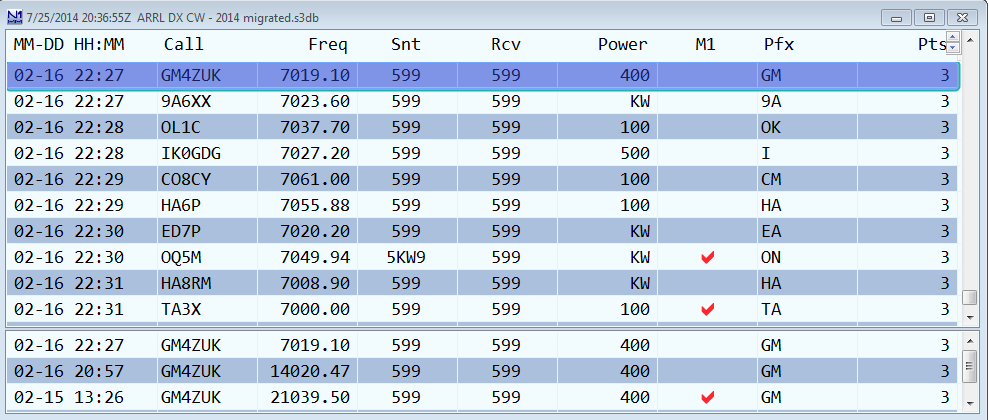
- The top pane is the log.
- The bottom pane shows the contacts in your log that match the partial or full call entered in the Entry window. It is sorted by band, call, date & time.
- The separator bar is set at a percentage of window size. When shrinking the window vertically, both sections get smaller. After resizing the window, decide how much space to allocate to dupes by setting the separator bar.
- The title bar gives date and time (in UTC), the selected contest and the name of the current database.
- To resize the text in the log, click on the resizer arrows at the upper right corner of the window.
- There are options for modifying the width of individual columns, to be found on the Right-Click Menu (see below). You can also resize them by click-and-drag of the invisible dividers between the header items. This will not work in the log itself.
- Click on the heading of any column to sort the log by that column. Click the header of the datestamp column (“MM-DD HH:MM”) to return to normal log order.
- When a Multi operator mode (Multi-One, Multi-Two, Multi-Multi) is selected, the “Op” and R# columns appear in the log, and the radio number and operator call-sign are shown for each QSO.
Editing the Log
Double-click any user-entered field in a QSO record to edit it; type the correction and hit Enter to save it. This can be done in either the upper or lower panes of the Log window, to facilitate correcting earlier QSOs with a station when you need to.
- Program generated fields, such as QSO points, cannot be edited.
- If you want to edit the sent serial number in a QSO, you will note that up/down arrows are displayed, on the assumption that you probably are just off by one. Click the appropriate arrow and hit Enter, or type the correction if you need to.
- If you want to edit the timestamp (date and time) of a QSO, first make sure that the date/time column is no wider than it needs to be. You can accomplish this, if there is white space to the right of the time, by right-clicking in the Log window and selecting “Auto Set Column Widths.” Now double-click on the time, and you’ll see the time in hours:minutes:seconds format, with the hours selected and a calendar icon with down arrow at the right end. If you need to enter a new hour, do so, and then hit Tab or Enter to exit. If you need to change the minutes, click on them with your mouse to select them, enter the new value, and hit Tab or Enter to finish editing. If you need to change the date, click on the down arrow next to the calendar icon, click on the date to change to, and hit Tab or Enter to exit.
- The Log window displays the RX frequency. If you want to change the RX & TX frequency use the right click – Edit Contact option.
When you edit one or more QSOs in the Log window, that might result in a change in the multiplier status of that QSO and/or in your claimed score. The score is not recalculated automatically when you edit QSOs, so you can end up with incorrect multiplier counts and claimed scores. To correct your claimed score after performing edits in the Log window, use the Tools > Rescore Current Contest menu item in the main Entry window.
Marking Multipliers
The check-marks denote whether a given QSO accounted for one or more multipliers. They are provided by the program based on the received exchange, callsign, and built-in data resources, such as the wl_ct.dat file. They cannot be edited.
Serial Numbers
In a serial number contest the serial numbers in the log window will be displayed without any leading zeros even when zeros are entered before the number (001 becomes 1, and so on).
Warning of Possible Errors
When a station is worked on multiple bands or modes with varying exchanges (zones 14 and 15, for example), this will be highlighted in red in the lower pane. The red highlight color indicates that there is a strong likelihood of an error.
Calls with no match in the master.scp file and zones that don’t match the country file will also be highlighted. The highlighting for no match in SCP file is the same color as the highlighted buttons in ESM, yellow/orange by default. This color can be changed in Config > Manage Skins, Colors and Fonts – it is the background color for highlighting text (the first entry in that dialog). This is usually not an error; the highlight is just a reminder to take a second look to make sure you typed the call sign in correctly.
These highlights only last for the duration of the contest. After the contest is over, the highlighting will disappear in order not to facilitate log washing after the contest.
Keyboard Shortcuts
- Delete (Ctrl+D) – Delete the last contact in the log.
- QuickEdit (Ctrl+Q) – Moves the last QSO in the log into the Entry window, and signals the mode with “QuickEdit” in the call-frame. You can tab or space through the window, make the changes you need, and then hit Enter to save them. Hit Esc to exit QuickEdit without making changes, or Ctrl+Q again while in this mode to switch to the next previous QSO.
Right-click Menu
Right-click in one of the rows in the upper pane – not in the title bar – and the following menu will appear.
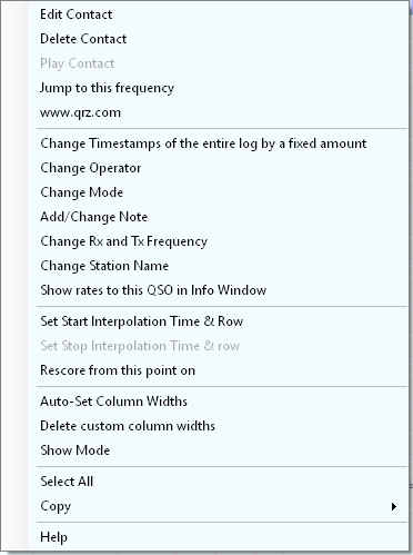
- Edit Contact – Opens a dialog to edit the selected contact – the one on which you click to open the right-click menu. Items which cannot be edited are greyed-out. This is mainly retained for those who have become accustomed to editing their log this way in N1MM Logger Classic.
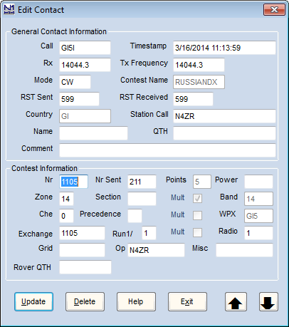
You can move up and down the log with the large black arrows.
- Delete Contact – Asks whether you want to delete the selected contact.
- Play Contact – Used to play back the selected QSO if recorded using the qsorder.exe program by K3IT (see References, Third Party Software). This selection will be greyed out if there is no recording. Contact audio will play on your default sound player. Make sure you don’t have the sound player connected to your radio’s audio input.
- Jump to This Frequency – Moves a connected radio to the frequency of the selected QSO. This can be useful in S&P mode if you look at the log after a couple of QSOs and discover a discrepancy that you need to ask the running station about.
- www.qrz.com – Opens QRZ.COM’s record for the call-sign in the selected QSO.
- Change timestamps of the entire log by a fixed amount – Useful when you discover your clock has been off since yesterday.
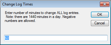
- Change Operator – Changes the operator credited with the selected QSO.
- Change mode – Changes the mode of the selected QSO.
- Change RX and TX Frequency – Allows you to enter a replacement frequency for that entered in the log for the selected QSO. Can be useful with a non-interfaced radio, if you discover that you forgot to log a band change.
- Change Station Name – can be used to change the station name of the PC that made the QSO.
You can also make the five types of changes above in more than one QSO at a time. Click the first log entry you want to change. Then either Shift+Click on the last QSO in a consecutive group, or Ctrl+Click on multiple non-consecutive QSOs. The highlighting for which lines are selected is very subtle in the default color scheme, so be careful.
When you have selected all the QSOs you want, right-click one of them to bring up the right-click menu, select the action you want, and fill in the replacement value. Hit Enter, and you’ll see a pop-up, asking you whether you really want to make this change in X QSOs. You can cancel at this point if you are not absolutely sure.
- Show rates to this QSO in Info window – If the Info window is open, displays QSO rate up to the selected QSO.
- Set Start Interpolation Time and Row – Used to adjust times in the log, often when entering contacts manually after the contest. An example of how to use this can be found in the After the contest chapter. This option is grayed out when networking is turned on.
- Set Stop Interpolation Time and Row – As above. After setting the start time and row, the end time and row can be selected, and then times on intervening rows will be interpolated between the start and end times. Not available in multi-computer mode.
- Rescore from this point on – Rescore from the selected QSO forward
- Auto-set Column Widths – A quick way to make sure column widths will suffice for the entire log, while minimizing the size of the log window. This option sets column widths based on contents, not the width of the headings, so some headings may be truncated in contests with short exchanges, for example.
- Delete custom column widths – Restores the default values, as defined by the length of the headings.
- Show Mode – Option whether to show a Mode column in the log – may be useful to help minimize the size of the Log window on a crowded screen in a single-mode contest.
- Select All – Select all the QSOs in the log for Copy to the Clipboard.
- Copy – Copies the selected QSO(s) to the Clipboard as either an ADIF string or a Generic string (used in European VHF contests).
- Help – Opens the manual page on the Log window (Internet connection required)
-3- The Bandmap Window
Your Bandmap window will be similar to this one.
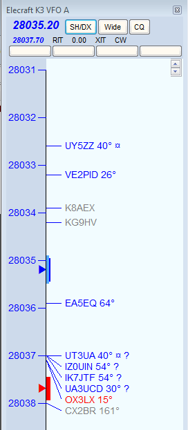
Key Features
The Bandmap window represents a VFO or a radio. There are three scenarios: one radio with 1 VFO displayed (SO1V); one radio with 2 VFOs displayed (SO2V); or two radios with one VFO shown for each radio (SO2R). Bandmaps can be zoomed down to just a few KHz or up to the entire band.
With one radio in SO1V mode, only one bandmap can be displayed. With one radio in SO2V mode, two bandmaps may be displayed, one for each Entry window. Each bandmap represents one VFO. With two radios the operation is exactly the same, except that each bandmap represents one of the radios.
To switch the Entry or RX Focus from one bandmap to the other, Press “\”. To switch both the Transmit and Entry/RX Focuses, press “Pause”.
The Bandmap window includes the following basic features:
- Current receiving frequency is denoted by a blue arrow. If split, the current transmit frequency is denoted by a red arrow. At the point of each arrow is a graphic depiction of whether the radio is currently in a wide or narrow filter setting for its current mode.
In this example, the radio is in the CW band. The dark blue and red bands are a notional (not actual) representation of the CW filter bandwidth, while the light blue represents the tuning tolerance set in the Configurer. If you tune the VFO outside that range, any call-sign captured into the Entry window’s call-frame or brought into the Entry window’s call-sign textbox will be erased. If you have elected to set the Config menu option “QSYing wipes the call and spots QSO in bandmap,” the station you did not work is spotted in boldface as a reminder to come back to it.
- The up/down arrows in the upper right control the size of text in the window, independent of the global setting for the rest of the program.
- In the title bar, the first line of smaller type shows the name of the connected radio, and the VFO or radio denoted by the Bandmap. Immediately below in larger type is the receiving frequency and below that, in smaller type, is the transmit frequency if different (when Split). To the right are three clickable buttons. The first sends SH/DX to the Telnet cluster to which you’re connected. The second toggles between wide and narrow filter settings, always displaying the one that will be selected next if it is clicked. Clicking on the third (labeled “CQ”) will jump your radio’s VFO to the last frequency on which you called CQ on the current band. The text CQ-Frequency is shown on the Bandmap on the frequency where you last went into Run mode, and used as the target for this function.
- Below the three buttons are text prompts to remind you that RIT or XIT are on (by turning red), report the amount of the RIT or XIT offset, and remind you what mode the radio is in. Each of these is clickable to turn the function off or on, or to step through the available modes – see Clickable Text Messages below.
- In the bottom line of the header are four programmable radio control buttons. Right-click on any of them, and an editing dialog will appear:
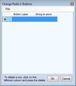
- The string to send is in the format of a radio control macro (e.g. CAT1ASC or CAT1HEX macro). Enter a label into the button label column and a radio control macro in the same format you would use in a function key message, including the curly braces. into the “String to send” column. Now clicking on this button will send the selected command to the radio. You can use “|” to set up commands and labels to toggle between the information on either side of the button. For an Icom 7300, here are some examples:
- Scope on|Scope off {CAT1HEX FEFE94E0271001FD}|{CAT1HEX FEFE94E0271000FD}
- 100w|50w|20w {CAT1HEX FEFE94E0140A0255FD}|{CAT1HEX FEFE94E0140A0128FD}|{CAT1HEX FEFE94E0140A0051FD}
- IP+ on|IP+ off {CAT1HEX FEFE94E01a0701FD}|{CAT1HEX FEFE94E01A0700FD}
- NR On|NR Off {CAT1HEX FEFE94E0164001FD}|{CAT1HEX FEFE94E0164000FD}
- NB On |NB Off {CAT1HEX FEFE94E0162201FD}|{CAT1HEX FEFE94E0162200FD}
- You can mouse over any call-sign on the Bandmap and a tool-tip will appear briefly, telling you when the station was spotted, by whom, and anything else about the spot. In addition, when a spot is less than three minutes old NEW will be placed behind the call and bearing on the Bandmap. When the spot includes split frequency information, the station’s receiving (QSX) frequency will be shown behind the bearing. Splits are shown as 3 digits on HF. The bearing to a station is shown only for stations outside your own country, with exceptions for USA and Canada.
- Spots of stations close to their sunrise/sunset time are marked with a sunrise/sunset indicator “¤”.
- CW Skimmer spots are marked with “#” in spotter’s call-sign as skimmer spot in the bandmaps (see picture at right above). If you are the spotter, then the spots are marked with a “!”.
Colors of the Incoming Spots
- Blue: Will be a good QSO, not a multiplier
- Red: Single Multiplier Example: CQWW – QSO is either zone or country multiplier (one multiplier)
- Green: Double or better Multiplier Example: CQWW – QSO is a zone and a country multiplier (two multipliers)
- Gray: Dupe
- Bold – This is a self-spotted call. In this context “self spotted” means that the user typed in the call, not that the spot came from the spotting network.
Note– A different set of color codes is provided for the WAE contests, to assist with QTCs. Read about it here
Display and Adjustment of Band Plans in Background of Bandmap Frequency Scale
The band plans (mode-based sub band limits) in the Bandmap window are important for other parts of the program besides the Bandmap window itself. These limits determine what mode the program assigns to incoming spots in the Telnet window if those spots do not contain the mode in the spot notes. This in turn can affect how the spots are filtered and whether or not they are passed from the Telnet window to the Bandmap and Available Mults & Qs window. Also, if the “Follow band plan” option has been chosen in the Configurer under the Mode Control tab, the mode that contacts are logged in will depend on the frequency. For these reasons it is important to understand how to set the sub band limits appropriately for the type of contest you are entering. The appropriate sub band limits can vary depending on the contest (DX vs. domestic, SSB vx. CW vs. digital vs. mixed mode). Inappropriate choice of the sub band limits is a frequent cause of logging errors.
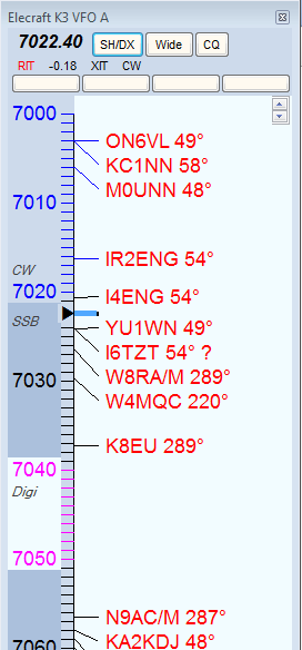
The illustration above depicts the new feature in N1MM Logger+ for displaying and modifying band plans. This is an alternative to the procedure provided on the Config menu of the Entry window. Note: This is not real – there is no digital sub-band inside the SSB portion of the band. It only illustrates all of the options.
There are some considerations to be aware of before you begin.
- You can only designate CW and digital band plan segments. It is assumed that anything not designated for one of those modes is SSB territory.
- You can only designate one band segment per mode, but by understanding the rules of precedence used by the program you should be able to handle this. For example, SSB is defined as not CW and not digital, so there is no need to set SSB limits.
To set the band plans from the Bandmap window, right-click on a frequency number in the Bandmap. That will bring up the following menu:
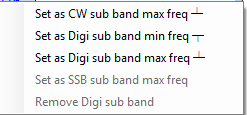
Instead of using this method, you may prefer to use “Change Band Plan” in the Entry Window, Config menu.
Note that you click on the frequency you want to set, and then click in the sub-menu to set it. For example, if you want to set the digital sub-band minimum frequency on 40 meters for a major RTTY contest, you might click on “7020” and then click “Set as Digi sub band min freq”.
- The “Set” options are self-explanatory. Options that are not available on a given band or frequency are greyed out.
- The “Remove” option is for CW contests, when many CW operators migrate into what are normally digital sub-bands. To prevent these being logged as RTTY, you can remove the digital sub-bands and re-establish them after the contest.
Keyboard Shortcuts
- Numeric keypad + key – Zoom In on the Bandmap associated with the Entry window that has entry focus.
- Numeric keypad – key – Zoom out on the Bandmap associated with the Entry window that has entry focus.
- Shift – Numeric keypad + key – In SO2V or SO2R, zoom in on the Bandmap associated with the Entry window that does not have entry focus.
- Shift – Numeric keypad – key – Zoom out on the Bandmap associated with the Entry window that does not have entry focus.
Jumping to Spots on the active radio or VFO (the one with the Entry focus)
- Ctrl+Down Arrow – Jump to next spot higher in frequency.
- Ctrl+Up Arrow – Jump to next spot lower in frequency.
- Ctrl+Alt+Down Arrow – Jump to next spot higher in frequency that is a multiplier.
- Ctrl+Alt+Up Arrow – Jump to next spot lower in frequency that is a multiplier.
Jumping to Spots on non active radio/VFO
- Ctrl+Shift+Down Arrow – Jump to next spot higher in frequency on the inactive radio/VFO. This will skip over CQ-Frequency when radios or VFOs are on the same band. Proper keystroke operation is radio dependent. Disabled for SO1V.
- Ctrl+Shift+Up Arrow – Jump to next spot lower in frequency on the inactive radio/VFO. This will skip over CQ-Frequency when radios/VFOs are on the same band. Proper keystroke operation is radio dependent. Disabled for SO1V.
- Shift+Ctrl+Alt+Down Arrow – Jump to next spot higher in frequency on the inactive radio/VFO that is a multiplier. If you are operating single mode, your mode won’t change when jumping between spots. Disabled for SO1V.
- Shift+Ctrl+Alt+Up Arrow – Jump to next spot lower in frequency on the inactive radio/VFO that is a multiplier. If you are operating single mode, your mode won’t change when jumping between spots. Disabled for SO1V.
- Shift+Alt+Q – Jumps to your last CQ frequency on the inactive VFO/radio. Disabled for SO1V.
Clickable Text Messages
These are found below the radio frequency at the top of the Bandmap.
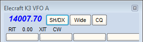
- RIT Offset (already 0.00 in the illustration) – Click this label to clear the RIT offset.
- RIT – Click this label to toggle the RIT on and off.
- XIT – Click this label to toggle the XIT on and off.
- CW/USB/LSB/RTTY/PSK/AFSK/AM/FM – Click this label to toggle from USB/LSB (band-specific) through RTTY to CW/PSK/AFSK/AM/FM (radio dependent).
Mouse Actions
- Click on frequency – Moves the active VFO/radio to that frequency.
- Shift+Click on frequency (SO2R only) in inactive Bandmap – Tune the non-active radio without changing window focus. Allows you to be active and sending on one radio and change the frequency on the non-active radio without changing Entry window focus.
- Shift+Click on bandmap callsign (SO2R only) in inactive Bandmap – Same as Shift+Click on Frequency with the addition that the callsign is placed in the non-active radio’s Entry window call-frame.
- Click on call – Jump to that frequency and place the call in the Entry window call-frame. When the call-sign field is empty, hit Space to copy the call-sign from the Entry window call-frame to the call-sign textbox.
- Double-Click on call – Jump to that frequency, place call in the Entry window call-frame and the call-sign textbox, replacing anything that was previously there.
- Click on or to the left of the vertical frequency scale – Jump to that frequency.
- Click frequency label – Jump to that frequency.
- Right Click call – Display the right-click menu for the selected call (see Right-Click menu below).
- The selected call will be shown in italic font and underlined when the right-click menu is open
- Right Click anywhere else – Display the right-click menu with some options grayed out which are call related.
Right-click Menu Options
If you right click in the Bandmap window the right-click menu will appear. If you do not click on a particular spot, certain options will be grayed out.

- Remove Selected Spot – equivalent to Alt+D with the spot callsign in the call-frame; removes the selected spot. Grayed-out when not right-clicking on a particular spot.
If your mouse has a clickable scroll wheel, you can also delete spots from the Bandmap simply by clicking on them with it.
- Blacklist callsign – if you click on this option and the Filter Blacklisted Spot Calls option in the Filters tab of the Telnet window’s right-click menu is enabled, subsequent spots of that station will not be displayed on the Bandmap or in the Available window. Used to get rid of busted spots that recur often, such as LW3LPL. To edit the list of blacklisted spots, or to remove a call from the list, use the Edit option on the filter tab.
- Blacklist Spotter – designed in particular for use when an RBN station is feeding spots that are badly off-frequency (due to I/Q image problems) or otherwise defective. Could also be used for the occasional harasser on traditional DX clusters. Again, this feature is enabled/disabled in the Filters tab of the Telnet window’s right-click menu; the blacklist can also be edited from that tab.
- Zoom In (Numeric Pad + or use the mouse wheel with the mouse over the Bandmap window) – Show a smaller frequency range on the Bandmap that has entry/RX focus; spreads frequency markers and spotted call signs farther apart.
- Zoom Out (Numeric Pad – or use the mouse wheel with the mouse over the Bandmap window) – Show a larger frequency range on the Bandmap that has entry/RX focus; brings frequency markers and spotted call signs closer together.
- Go to Bottom of Band – Go to the bottom of this SSB/CW subband.
- Go to Top of Band – Go to the top of this SSB/CW subband.
- Remove Spots, This Band Only, Leave Self Spots
- Remove Spots, This Band Only
- Remove Spots, ALL BANDS, Leave Self Spots
- Remove Spots, ALL BANDS
- Show Last 10 Spots – click this option (which is gray unless a callsign has been clicked on) and the cluster will be asked for the last 10 spots of that station. These are displayed in the Telnet window.
- Show QRZ – requests address information from the DX cluster
- Show Station – sends the SH/STA [callsign] command to the DX cluster
- Show QSL/Packet – sends the SH/QSL [callsign] command to the DX cluster
- Show Sunrise/Sunset – sends the SH/SUN [callsign] command to the DX cluster
- Set transceiver offset frequency – This is for transverter support. The offset is saved when the program closes and read again when opened. Remember to enter the frequency of the transceiver and not that of the transverter when going into split mode (Alt+F7). Information how to fill in this table (which frequencies to enter and how to calculate the IF frequency) can be found in the VHF and Up Contesting chapter.

- Set transceiver timeout time – Sets the time interval after which, if no communication with a radio is occurring, the program will alert you. The value is set for each radio (default is 15 seconds). Entering a value of zero will disable the timeout function. Entering a negative number will set the time out value to 15 seconds. Entering a number that is too large for the program variable will set the timeout to the program maximum. The positive minimum is 5 seconds.
- Set transceiver filter codes – This setting controls what is sent to your radio when you click the “Wide/Narrow” button at the top of the Bandmap to toggle between wide and narrow filters. If no value is set, then the program uses the default values set for your radio.
You will be prompted for the wide or narrow string to set the filters. For Kenwood, it’s pretty easy. You just look up in your manual the string you want and enter it. For other radios, like FT-1000MP, it’s harder. You must enter a series of space-delimited codes in DECIMAL. Therefore, when an FT-1000MP filter code of 0 0 0 0 8C is required, you must enter 0 0 0 0 140 (8C hex).
To reset to the default values in the program enter a space and press the OK button. It is possible to use {CR} in the filter codes which will be replaced with the return character. These selection are disabled when manual radio is selected (i.e. no radio selected).
- CW Wide
- CW Narrow
- SSB Wide
- SSB Narrow
- Digi Wide
- Digi Narrow
- Find a Callsign (use Alt-F8 to return) – This option allows you to search for a particular callsign in the bandmap. Searches from current frequency up to find each instance.
- Bring to foreground when made active – This brings the active bandmap to the foreground. If you don’t have enough monitor space, you can place Bandmaps on top of one another, and when you move the entry focus between Entry windows, the active bandmap will be shown hiding the non-active bandmap.
- Reset Radios – Allow manual reset of all attached radios. When contact with a radio is lost the dialog below will appear at the bottom of the Bandmap window. The “Radio Problem” popup will disappear after a few seconds, but the “Reset Radio” button will remain until communications with the radio has been restarted. Once any physical problem (such as a disconnected cable) has been corrected, you can click on the “Reset Radio” button or right-click on the bandmap and choose “Reset Radios” from the right-click menu to restart the connection.
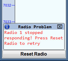
- Telnet Bands/Modes – opens the Bands/Modes tab of the Telnet window so you can adjust which bands and modes will be displayed on Bandmaps and in the Available Mults & Qs window.
- Telnet Filters – opens the Filters tab of the Telnet window so you can adjust which spots will be displayed on Bandmaps and in the Available Mults & Qs window.
- Show Telnet History – Shows the Telnet history of any station on the bandmap. Select the station by right-clicking on it and then clicking on this option.
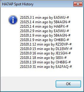
- Show My Call Spot History – Shows the recent Telnet history for spots of your station.
- Help – Show the help file for this window.
When the cluster to which you are connected is a DXSpider cluster, select ‘Format for DX Spider cluster’ on the Other tab in the Configurer.
Hovering with the mouse over a spot
Hovering with the mouse over a spot in the Bandmap gives the following info about the spotted station:
- Exact frequency sent by spotter.
- Call-sign of spotter.
- The time in minutes since the station was placed on the DX cluster network.
- Comments sent with the spot.
- The notation “Self Spotted” indicates that you spotted the station.
Hovering with the mouse over the blue arrow marking your receiving frequency – shows the exact frequency and tuning tolerance.
Example Bandmap Usage
by Tom, N1MM
In Search & Pounce (S&P) the call-frame will show you each spotted station as you come within “tuning tolerance” (user settable) of that station. I’m terrible at remembering whether I worked a station and on what frequency. With worked stations in the bandmap, the program will tell you that they are not workable again. You can tune by them more quickly. The same feature is useful in contests with unworkable stations.
In a contest like CQ WPX, with (basically) no value multipliers, here is how I use the Bandmap. Whenever I can’t get a run going I start S&P on a band with a lot of unworked stations (use the available window). I use Ctrl+Up and Ctrl+Down arrow to go to the next station. If that station is at the beginning of a QSO, I move to the next one. If the QSO is near the end, I wait and work the station. Then I move on. If I reach the top of the band, I start coming back down the band, working the ones I missed on the way up. If there is no station at a frequency, that’s my new running frequency!
In contests with valuable multipliers, you should use Ctrl+Alt up/down to get the multipliers first, then go back and get the QSOs.
If the rate drops fairly low, sweep the band using your VFO. That is where the old calls in the bandmap come in useful. If you copy a call, but it seems like it is going to take a long time to work him, tune to the next guy. If you have “QSYing wipes the call & spots QSO in bandmap” turned on, the call will be spotted in bold, so you can Ctrl+Up/Ctrl+Down to him later.
Remember: if a call is in the callframe, space will load it into the call textbox.
If all this seems very unfamiliar, you haven’t read the Key Assignments help (and/or the Key Assignments Shortlist).
Reading that single item is your single best time investment in using this program.
Spots and the time shown
When you hover with the mouse over a spot in the bandmap, it will show the relative age of a spot in minutes. The time shown here depends on the spot format. There are two formats for spots. One is for current spots, one is for SH/DX spots. Some clusters allow to show old spots in the current spot format. The program handles the two types of spots differently.
- Current spots go into the bandmap with the computer’s local (converted to UTC) time. This is to remove variations in cluster times and order the spots into the time they were received.
- Old spots are logged with the originating cluster’s time with the provision that it cannot be later than the current local (UTC) time.
With AR-Cluster you can display old spots with SH/DX or SH/FDX. It is recommended to use SH/DX, as it will be recognized as an old spot. Other cluster software may have similar capabilities.
Red lines indicating US license frequencies
On the bandmap there are red lines to indicate extra, advanced and general portions of each band. Since US hams can operate only in their section and the sections of lower class licenses, it is in your interest to operate some in the higher portions of each band. Otherwise there are some US hams you will not ever be able to work.
The lines can be found on:
- SSB: 3775, 3850, 7225, 14175, 14225, 21225 and 21300.
- CW: 3525, 7025, 14025 and 21025.
- No lines on 160 and 10 meters.
-4- The Telnet Window
Your Telnet window will be similar to this one, with six tabs.
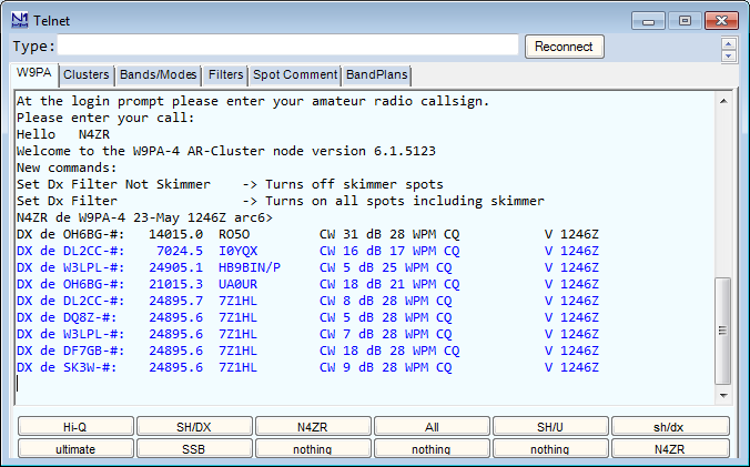
- The textbox labeled “Type:” is where you can input any text commands to send to the cluster. For example, typing “bye” without the quotes and hitting Enter will disconnect you from most clusters.
- The “Reconnect” button will re-establish your connection to the cluster shown on the label of the first tab (see below).
- A font sizer is at the upper right, just below the “X” to close the window. Click the up or down arrows to change the size of the text in the text pane below.
- The text pane is where all messages from the Telnet cluster will appear. Click in the text pane to temporarily halt scrolling; move the mouse cursor out of the text pane to restart it.
- All incoming information from the connected DX cluster is displayed in the text area of the Telnet window. They are color-coded by mode – defaults are blue for CW, magenta for digital, and black for SSB. Spots forwarded to the Bandmaps and Available Mults & Qs window are filtered as provided on the Filters tab. Spots that are filtered out (not forwarded) are greyed out in the text area.
Split information given in the spot comment will be recognized and forwarded to the Bandmaps and Available window. When such a spot is selected the transceiver will go into split mode (if applicable). The program recognizes: UP, U, DOWN, DN, D and the word QSX. Examples: QSX 3.838, QSX 4, UP 5, DOWN 2, U 5, D4, U4, DN4, UP4, DOWN4, QSX7144 etc.
Tabs
There are six tabs above the text pane, which is displayed by default and also tied to the left-most tab, which always displays the call-sign of the currently-selected cluster.
The first tab displays the callsign of the Telnet cluster node to which you are connected, and opens the lower pane so that you can see the flow of spots from the node. Except as noted, any changes made on the other tabs take effect when you switch back to this tab.
Clusters (including problems connecting)
The Clusters tab is used to select the cluster to which you want to connect, from a list that you can also edit from the tab. The Edit List button in the window under the Clusters tab opens a new edit window where you can make changes to the list. You can import or export the list of clusters from/to a file using the File menu in the edit window. By default, these files are stored in the ExportFiles folder in the N1MM Logger+ user files area.
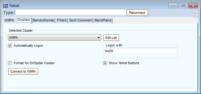
Also on the tab:
- A checkbox to tell the program to automatically log on to the selected cluster whenever the Telnet window is open.
- A checkbox to format some commands properly when you are connecting to a DXSpider cluster.
- A “Logon with” field, where you fill in the callsign the cluster is expecting to see at logon.
- A “Show Telnet Buttons” checkbox. Uncheck it to reduce the size of the Telnet window as much as possible, saving screen space.
- A “Connect” button that will send the logon sequence to the selected cluster and switch your view of the window back to the selected cluster.
If you cannot connect to a cluster check the following:
- Edit the clusters list and make sure that the domain name of the cluster is correct.
- Edit the clusters list and make sure the port of the cluster is correct and it is separated from the domain name by a colon (:), e.g. k1ttt.net:7300
- Disable your anti-virus software and (re)install the latest update. Test the connection. Reenable your anti-virus software.
- Check your software firewall to make sure N1MM Logger+.exe is allowed to connect externally.
- Check your hardware firewall to make sure that connecting to port 23 (default) or port nnnn (as specified in the cluster list) is allowed.
- Try testing using the Windows Telnet program to connect. For Windows 10, you can enable Telnet by going to Programs and Features, Turn Windows Features on or off, select Telnet client and press OK.
- Connect via Telnet by issuing the following command in the Windows command box next to the Windows button: Telnet , e.g. Telnet dxc.w9pa.net 7373 If this connects, it means that you have the wrong dns or port, or that something in your machine is blocking N1MM Logger+ from connecting.
If you are using N1MM Logger+’s networking to connect multiple computers together in a network, only one of the computers in the network (the one designated as “Master”) connects to a Telnet cluster. The other, non-Master computers need to have their Telnet windows open to receive spots from the Master computer, but they do not connect directly to a Telnet cluster.
Bands/Modes
The Bands/Modes tab allows you to select which bands and modes will be passed through to the Bandmap(s) and Available Mults & Qs window. Select bands individually or select groups of bands with the large buttons across the top (“HF”, “VHF”, etc.). Select mode(s) individually, by clicking the “All” button, or by checking “Contest” to pass only the mode(s) valid in the current contest. The “Reset All Defaults” button will check every band and mode.
Note that if any of the check boxes in the mode column is/are checked, spots for that or those modes are the only ones that will make it through the filter. The sub-bands set up in the Bandmap window for CW, Digital and SSB can have a major effect on this, too. Any spot that does not have its mode mentioned explicitly in the spot notes will be assigned a mode based on its frequency relative to the Bandmap window band plans, and spots that have been assigned a mode that is not checked will not be passed through. If spots do not seem to be getting passed from the Telnet window to the Bandmap and Available windows, check the sub-band definitions in the bandmap as well as the mode and band check boxes in this window.

Filters
The Filters tab provides another set of filters, as well as checkboxes for a few related options.
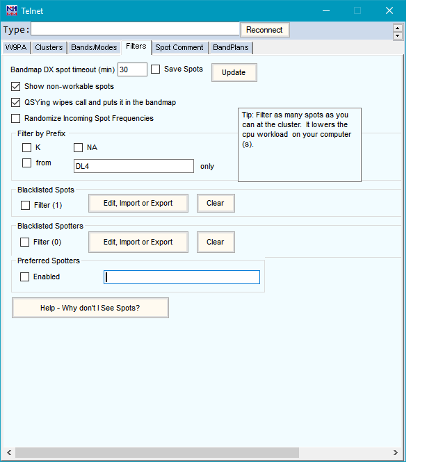
- Set the desired Bandmap timeout for DX spots by entering time in minutes.
Save Spots
The “Save Spots” checkbox is a new feature, added to solve an issue with packet spot processing that caused the spots database (Spots.s3db in the Databases folder) to grow too large and impact program performance. If you are experiencing symptoms of this, check the size of your Spots database. If it is more than a few MB, that may be why.
The “Save Spots” box is unchecked by default, and if left that way, the Spots database is not used at all. The advantage is very low performance impact from Telnet use. The drawbacks are that when you restart N1MM Logger+, the Bandmap will be empty. The check for Telnet spots in the Check window will not be active, and the “Spotted” option in the Multiplier window will not work.
If the box is checked, N1MM+ now honors the Bandmap timeout value set on this tab. For example, if you set the timeout value at 20 minutes, the Spots database will only retain spots for the last 20 minutes. When you restart NL+, the Bandmap will only display spots for the last 20 minutes, and the Check and Multiplier windows will only use spots from the last 20 minutes. The developers are aware that the latter is a slight drawback, and may look at other options after the high contest season is over.
Show non-workable spots and QSYing wipes call and puts it in the bandmap
These options have the same effects as the corresponding entries in the Config menu in the Entry window. “Show non-workable spots” will display duplicate or zero-point call signs so you know to tune past those frequencies instead of having to stop and listen to determine whether the station is workable. The “QSYing wipes” option automates the adding of spots to the bandmap when you are S&Ping. If you enter a call sign in the Entry window and then tune away, perhaps because the pileup is too large at the moment, the call sign will be placed in the bandmap, marked with its multiplier color status, so you can easily tune back to it later (or avoid that frequency if it is a dupe). If you work a station and then tune away, and if “Show non-workable spots” is selected, the worked call sign will be placed in the bandmap in grey as an indication that the station on that frequency has been worked. By default these spots to the bandmap are local only, i.e. they are not sent to the spotting network unless you have also selected the Config > Spot All S&P QSOs option in the Entry window.
Randomize incoming spot frequencies
Automatically adds or subtracts a small amount from the received spot frequency, so as to improve your chances of breaking a “packet pileup” when you click on a spot.
Spot origin filtering
If you only want to see spots originating (i.e. the spotter’s location) in certain countries or areas, you can use the Filter by Prefix area to limit the spots to those from your own country, continent or specific call area(s) using the check boxes in the top row, and/or by entering country or call area prefixes in the text box in the second row, separated by spaces. Beware: if anything is checked in this section, the *only* spots that will make it through the filters are those that meet the prefix, country or continent criteria you have checked or entered into the list.
The filtering capabilities of the cluster node are usually more powerful and flexible. Using them also reduces telnet traffic and the processing load on your computer’s CPU by limiting the number of spots sent to your computer from the cluster node. Generally, we recommend that you use the spot filtering at your chosen Telnet cluster where possible.
Spotter and spotted station blacklisting
You can “blacklist” either specified spotters or specified stations spotted, or both. The Edit, Import or Export buttons allow you to create and edit lists of stations whose spots you do not want to see, while the Clear buttons allow you to clear the list and start over. In both cases, the feature is enabled by a check box, i.e. you can create a list but only enable it in certain contests or at certain times. This filtering acts in addition to filtering by origin, or by bands and modes, i.e. the various filters are cumulative.
Preferred Spotters
When enabled, this command permits listing 1 to 3 spotters whose spots you wish to have highlighted in all windows where spots appear. Enter the preferred spotters’ callsigns in the box, separated by spaces. This is particularly designed to highlight a local Skimmer if you have one.
As an added touch, the three preferred spotters can each include variations on the base callsign. Hence, listing WZ7I will also highlight WZ7I-2, WZ7I/3, etc.
Spot Comment
This tab lets you specify a comment for each spot you make (such as “WPX”) and add log data fields to the fixed comment.
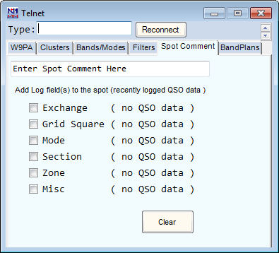
Band Plans
The Band Plans tab formerly permitted setting limits for mode segments within band plans. This function has now been moved to the Bandmap window, and is accessed by right-clicking on a frequency label (e.g. “7045”) in the Bandmap window.
Nevertheless, even though this function is no longer carried out from the Telnet window, the choice of sub band limits in the Bandmap window can have a significant effect on telnet spot processing. Spots that do not have a mode designated in the spot notes will be assigned a mode based on those sub band limits, regardless of whether the Bandmap window is actually open or not. If the sub band limits are not set appropriately, this can result in incorrect modes being assigned to spots, which can in turn affect how those spots are filtered and processed, and whether or not the spots are displayed in the Bandmap and Available Mults & Qs window. The sub band limits are not set based on FCC regulations, as new US licensees might expect. The appropriate sub band limits vary depending on the nature of the contest (CW vs. SSB vs. digital vs. mixed mode, domestic vs. DX contest). It is up to the user to set the limits in the Bandmap window according to the patterns of usage in the current contest.
For example, in a DX phone contest you might need to set the top of the 40 meter CW sub band very low in the band in order to ensure that spots of DX stations operating split, transmitting below 7100 kHz and listening higher in the band, show up on the bandmap and in the Available window. On the other hand, if you leave this same setting in place for a CW contest, that could result in CW spots being missed because the program assigns unlabeled spots of CW signals to SSB. To prevent this, you will need to manage the location of the CW vs. SSB sub band limit in order to ensure that it is consistent with the current situation.
If you want to use spots for a digital contest, you may need to define digital sub bands for each band in the Bandmap window. On 40 meters, the appropriate location of the digital sub band will depend on whether the contest is a DX contest or a domestic North American contest. After the digital contest is over, if you don’t remove or adjust the digital sub band, some CW spots might get missed because the program assigns a digital mode to them based on the sub band limits in the Bandmap window.
Sending Stored commands to the cluster
Across the bottom of the Telnet window are twelve buttons which can be individually programmed with stored messages to be sent to the Telnet node. Right-click in the button area to bring up the editor.
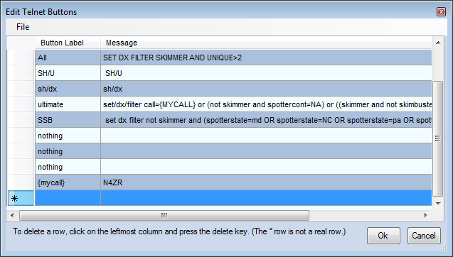
Different button sets can be saved and recalled for use with the File menu at the upper left. By default the text files containing sets of button messages are stored in the FunctionKeyMessages folder in the N1MM Logger+ user files area.
You can also use one or multiple buttons to store a quick-connect command to connect to a specific telnet cluster. The syntax expects a ‘{CONN} node’. Example: Assuming you have added a cluster with the name RBN to the list of clusters, you can assign it to a button by adding ‘{CONN} RBN’ to a button value.
Mouse Clicks
- When the you left- or right-click in the text area, scrolling is stopped. A right-click on a callsign brings up a small menu
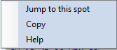
Click on “Jump to this spot” to send the active radio to the spot frequency. This option is mainly retained for nostalgia. It makes far better sense to click in the Bandmap or the Available window while maintaining the Telnet window minimized, once you have the filters, bands and modes set up as you want them.
Multi-User Setup
When running in networked computer mode, only the Master station has to be connected to the DX-cluster. The master station will relay all information to and from the connected computers to the cluster node.
CW Skimmer and the Reverse Beacon Network (RBN)
CW Skimmer version 1.1 and up has a built in Telnet server which allows N1MM Logger to receive spots from it. Add an entry to your Telnet list with the address: 127.0.0.1:7300 if you are running Skimmer on the same machine as N1MM Logger. If running on a different PC on the same network, use that machine’s internal IP address in the same format.
The Reverse Beacon Network’s Telnet relay servers make all of the RBN’s Telnet spots available to users worldwide. Because of the huge volume of spots on a major contest weekend – at least fifty times as many as the conventional cluster network – we highly recommend that you connect to a “retail” server and use the node’s filtering capabilities to manage the quantity actually sent to you. It will be helpful to use a short Packet Spot Timeout (set on the right-click menu of either the Bandmap or on the Filters tab of the Telnet window) – 15 minutes should be more than adequate, because CW Skimmer re-spots stations that remain on the same frequency every 10-12 minutes.
Because of the high volume of spots, the RBN uses specially-designed relay servers on its Telnet nodes, which are internally streamlined. A side-effect is that these nodes do not respond to user commands. This is another good reason to connect to a “retail” cluster that handles both RBN and traditional spots. You can find a list at this site .
Local Skimmer spots can be merged with spots from conventional DX clusters using software such as WintelnetX or CC User, freeware by K1TTT and VE7CC respectively. Skimmer spots are distinguished from regular spots by the addition of unique markers. In the Bandmaps, Skimmer or RBN spots are identified with “#” after the callsign and bearing; spots from your own Skimmer, identified by the callsign set in your Station Data), are marked with “!”
Spot Filtering
There are three levels of spot filtering available. The first and most powerful of these using whatever filtering capabilities are built into the node. The second is established by the Band/Modes and filters tabs of the Telnet window. A third is set by the Available Mults & Qs window’s Bands and Modes button. The latter only affects what is seen in that window.
AR Cluster V6’s Skimmer Spot Quality Filtering
Because of the large volume of spots generated by the RBN, even at very high accuracy rates (over 99 percent), a large number of busted spots have been noticed. Toward the end of major contests, these may be a significant problem for serious competitors. In addition, calibration and image errors are occasionally encountered due to hardware and software issues.
CT1BOH has developed and AB5K has implemented DX cluster-based evaluation of spot quality, in an effort to reduce the number of bad spots seen on the RBN. This nice piece of work was implemented in Version 6 of AR Cluster. AB5K.net was the first node offering this feature, and many more now have it too. You can find an exhaustive list at this web site.
The evaluation is subdivided into 3 categories:
- Validation – When a callsign is first spotted on a given frequency, it is tagged with a “?” in the last column of the Comment field of the spot. When two or more other RBN nodes agree on the spot, the tag on each subsequent spot becomes “V”
- Frequency – After a station has been spotted on a given frequency, if it is then spotted on another frequency the spot is tagged as above, but with a “Q”, for QSY? Again, once the move is confirmed, subsequent spots are tagged with V. The idea here is to catch I/Q image spots, spots sent by badly-calibrated Skimmers or spots inadvertently sent on the wrong band.
- Busted Spots – This is the real high point of the Quality Tags. The algorithm uses some sophisticated measures of the “resemblance” between the busted spot and the real one, and will tell you both what spots are busted and what the real call is, based on other spots at or very near the same frequency.
Here is a brief snapshot of one minute of RBN plus traditional spot flow.
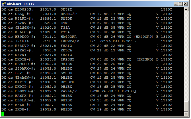
You can see that the node software picked up two busted spots, and also was skeptical about others until they were repeated. There are no QSY spots in this sampling, but if there had been, you would have seen the “Q” tag.
When you first connect to an AR Cluster, make sure it is sending RBN spots as well as traditional ones by commanding it to “set dx filter”. Once RBN spots are flowing, you can set any other filters you want to, such as limiting spots to stations in your geographic area. Then all you have to do is send “set DX extension skimmerquality”, and the Quality Tags will start to appear at the right end of the Comment field.
Some operators will prefer to filter out certain of these spots. Most likely candidate for this treatment are spots tagged with “B”., but you can filter out “?” or “Q” spots too, and the node will not send spots of those stations to you until they are confirmed (and tagged V). Here’s a partial list:
Set DX filter Skimbusted – only send me those spots that are marked as busted, together with the node’s identification of the correct spot)
Set Dx Filter NOT Skimbusted – don’t send me any spots that are tagged as B
Set DX filter NOT SKimQSY – don’t send me any Q spots until they are verified
Set DX filter Skimvalid – only send me spots that have been tagged with a V
These and other Skimmer-related filtering commands are found on AB5K’s website.
One of the neat things about AR Cluster V6 is that you can create complex filters to show you exactly what you want. For example:
SET DX FILTER {MYCALL} OR (spotterstate=MD OR spotterstate=PA OR spotterstate=VA OR spotterstate=WV)
This filter will tell me whenever I am spotted anywhere in the world, and otherwise will show me all spots, both traditional and RBN, made by stations in the states around my QTH.
While N1MM Logger+’s Telnet buttons will accommodate fairly long commands, stringing together a lot of “state=” or “cty=”, or “state<>” or “cty <>” commands could be too much. Fortunately, there is an abbreviated syntax. The “[entity]=/<>” filters can be abbreviated as follows:state=[MD,VA,WV,PA] or CTY=[K,VE,KP4]
You could add some Quality Tag-specific filters – for example:
SET DX FILTER call={MYCALL} OR NOT skimbusted and (spotterstate=md OR spotterstate=pa OR spotterstate=va OR spotterstate=WV)
This filter will work the same as that above, but also will not show me any spots that the cluster evaluates as busted.
Here’s another filter that lays on some more complexity, written by CT1BOH and recently published on CQ-Contest:
Set DX Filter (skimValid OR not skimmer or ((SkimQsy OR SkimUnknown) AND (cty <> K AND cont <> EU )))
This filter shows human spots, Skimmer spots appraised as V(alid), and Q and ? spots from outside Europe and the USA. It filters out Q(new frequency?) and ? (not yet valid) spots from the US and Europe, on the theory that it’s less important to jump on those first.
So that’s the story – whether you choose to filter at the cluster node, or see everything coming in and make your own decisions, Quality Tags can be a very useful tool. Congratulations to CT1BOH and AB5K for their achievement.
Using Filters
Many operators will prefer to make their own judgments, rather than using filters. There are some advantages to this, probably. For example, a rare multiplier spotted initially by only one RBN node would carry a “?” tag until two more confirm the spot. Waiting for it to come through a Skimvalid filter could result in your being twentieth in the pileup instead of first or second. Late in a big contest, a large multi-op will have worked many of the stations on each band. A lot of busts will seem to be valid, but operators may want to make that judgment quickly for themselves rather than relying on the node. The next section shows how you can use N1MM features to make this approach easier.
N1MM Logger has two main ways of initiating S&P QSOs, by using either the Available Mults and Qs window or the Bandmap(s). Of the two, the Bandmaps are the easiest way to work with Quality Tags, simply because the Available window scrolls so quickly when receiving spots from the RBN. Just mouse over the callsign on the Bandmap that you wonder about, and the full spot, including the Quality Tag, will appear in a tooltip. This makes it really quick and easy to skim over the bandmap and dismiss the busted ones with Alt+D Here’s an example
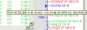
In this example, if you had worked EA1FAI a couple of minutes before, when you saw EA1FAE pop up, you moused over him, and he was revealed as a busted spot. Alternatively, you can click on a call to select him for a possible QSO, and if the tooltip reveals he’s a bust, you just hit Alt+D and move on.
Spot Flow in N1MM Logger+
The following diagram may help you visualize how Telnet spots flow through N1MM Logger+
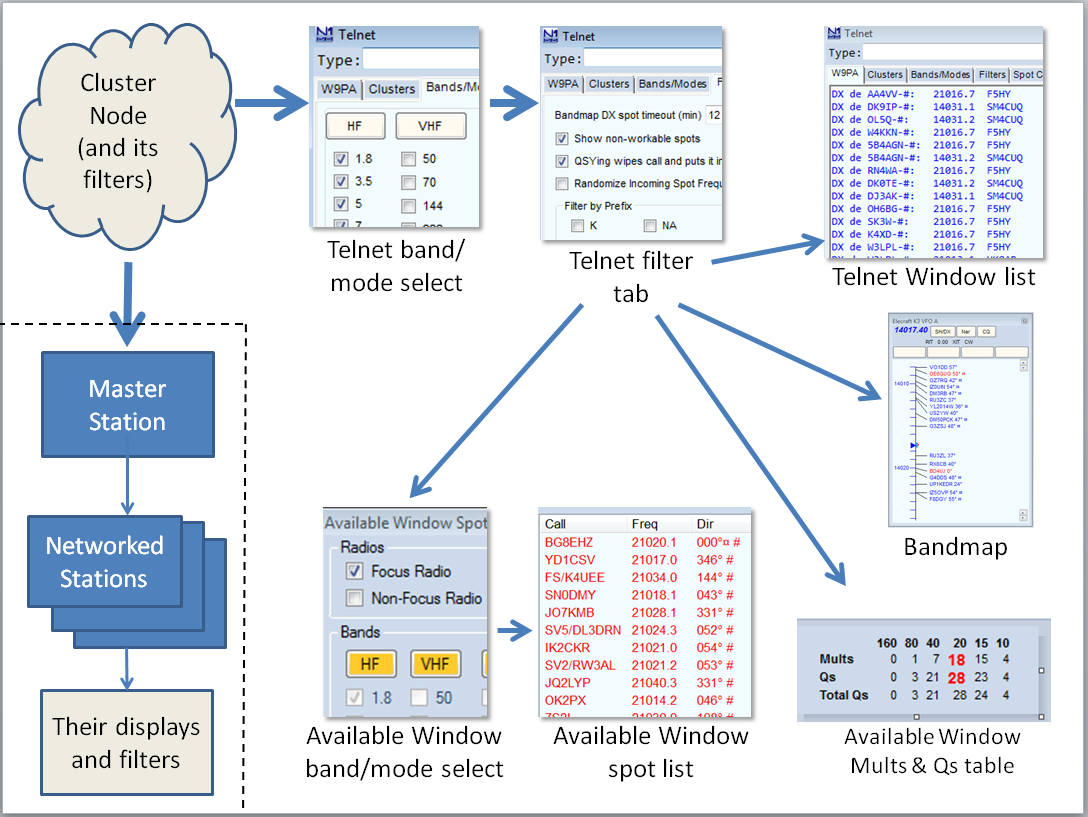
The Available window band/mode settings only affect what is displayed in the Available window’s spot list. Spots flow to them through the band/mode and filter tabs of the Telnet window, and so must be the same as, or more restrictive than, those settings. If you discover that certain band or mode choices are greyed out, take a look at your Telnet window settings. Also, check to make sure that the sub band limits in the Bandmap window are set appropriately. Inappropriate choices for the sub band limits can result in spots being assigned to the wrong mode and being greyed out as a result.
In networked-computer mode, spots flowing to the Networked Computers are not affected by any filter settings in the Master Station. Networked Stations’ spots arrive unfiltered, in order to let the operators at those stations set their own filters in N1MM Logger+.
-5- The Check Window
Key Features
The N1MM Logger+ Check window is the latest evolution of the Super Check Partial idea originated by K1EA in the CT logging program. It combines up to four separate sources for checking the validity of an entered or spotted call-sign. Its system of color-coding helps the operator determine if the call-sign as copied is correct, and, if not, where the error probably lies.
When first opened, before a partial or complete callsign is visible in either the callframe or the call-sign textbox of the Entry window, the default Check window looks like this:
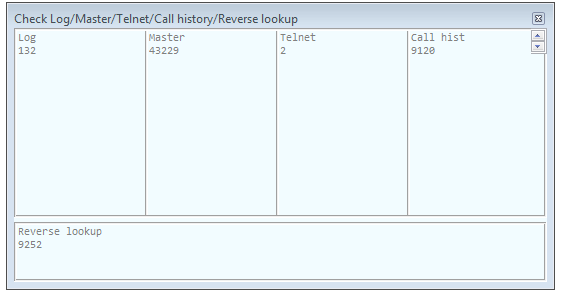
The four upper panes, left to right, will contain results derived from comparison with your current log; with a Master.scp data file downloaded on the Tools menu of the Entry window; with Telnet spots received by the program, and with a Call History file, if one has been loaded. The numbers immediately below the grey pane titles reflect the size of the files under comparison, at the moment the check window was opened. The log and Telnet totals will continue to grow for as long as the underlying database tables continue to grow, but will not be seen again until you re-start the program.
The bottom pane is for Reverse Call History Lookup, discussed below.
You do not have to display results from all these sources, or from the reverse lookup window. A right-click menu lets you uncheck any panes you do not wish to see:
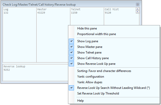
The other choices on this menu will be discussed below.
- When you enter a call-sign in the Entry window’s call-sign textbox, beginning with the third character, or a call-sign is transferred into the call-frame from the Bandmap, the Check window will begin trying to check it against the selected sources of information. The check results are displayed as below, using “YT1” as an example:
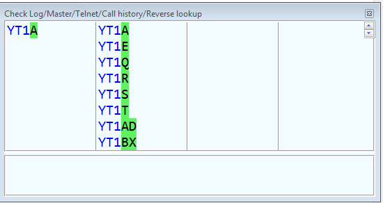
Note the green highlights – given the first 3 characters, the Check window is telling you that there are matches with those characters, and that any of the callsigns with one or two green-highlighted characters could be correct, based on what has been found in the various call-sign files.
Now enter another character, making the possible call-sign YT1E. The Check window changes:
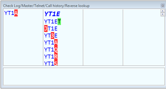
In the first row, the bold and italicized callsign reflects a perfect match in the master file. “YT1A” with the “A” highlighted in red means that an imperfect match was found in the current log – you may actually have heard YT1A rather than YT1E, since the station has already been logged once in the contest.
There is another list of suggested call-signs in the master file pane. The first, with the green highlight, means that “YT1E” matched a call in the master file, but only in part. The full call found in that file is YT1ET, so the “T” is highlighted in green. But there are other possibilities, if you miscopied one of the characters. Each of the characters that would have to be changed is highlighted in red.
Special Telnet Features
Because of uncertainty about the quality of Telnet spots, a spot will only appear in the Telnet section if:
- It has been spotted at least 3 times or
- It has been spotted with a Q or V spot-quality tag on AR Cluster version 6.
- If the Save Spots checkbox on the Filters tab of the Telnet window is checked, this check of Telnet spots will be retrospective to the beginning of the current contest. If it is not checked, the retrospective check is limited to the Packet Spot Timeout interval set either on the Filters tab or on the Bandmap’s right-click menu.
Reverse Call History Lookup
In contests where this feature is supported you may enter a sought-for multiplier (for example, a rare county in a QSO party) in the Exchange textbox of the Entry window. The call-signs of any stations with that multiplier in either the current log or the Call History file will then be displayed in the bottom pane of the Check window. A full description of the Reverse Call History Lookup feature may be found here.
Right-Click Menu
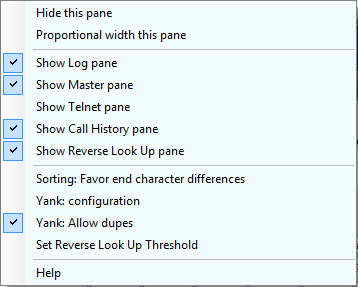
The right-click menu contains user-selected options for the Check window, along with some actions that can be taken “on the fly.” It is opened by clicking in the text area of the Check window (not in the header).
- Hide this pane – used to get rid of a pane in the Check window quickly. Right-click in the target pane and click this option to hide it.
- Proportional width this pane – This feature can be used to make one section of the Check window larger than others. Right-click in the pane you want to enlarge, select this option, and enter a number in the pop-up dialog that appears. Panes are all the same width by default, so entering “2” will make the target pane twice as wide as the others, “3” will make it three times as wide, and so on. This choice remains in effect until the Check window is closed and reopened.
- The next five checkable options determine which panes appear in the Check window. If you are not running Assisted, for example, there is no reason to display the Telnet pane; if you have not loaded a Call History file, you can hide that pane, and so on.
- Sorting: Favor end-character differences – Used to determine how much weight to give the last character in an entered call sign. This will help determine how high up the listing of possible calls a call sign with a /P, for example, might appear.
- Yank: configuration – The hot-key Alt+Y can be used to “yank” a call sign from the Check window into the call sign textbox of the Entry window, replacing what is currently there. Clicking this option on the right-click menu opens a sub-menu:
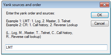
This sub-menu determines the panes in which call signs will be selected for yanking and the order in which those panes are selected with consecutive yanks. In this example, with LMT entered as the Yank order, the Log, Master and Telnet panes will supply the call signs to be yanked. The first Alt+Y will yank the first call in the top row in the Log pane. Subsequent Alt+Ys will step through the calls in the top row in that pane, and then do the same in the Master file pane, and then in the Telnet pane. After the first row in all the panes has been exhausted, the next Alt+Y will yank the first call in the second row in the Log pane and proceed through the second row in the three panes in the order specified, and so on.
- Yank: allow dupes– As the name suggests, checking this option will allow you to yank call signs which are in your log and reported as dupes.
- Set Reverse Lookup Threshold – opens a sub-menu where you can select how many characters must be entered in the Exchange field before the Reverse Lookup occurs. When using a very large Call History file or operating in a QSO party such as 7QP where the first two letters of each multiplier only denote the state, increasing the threshold above the default “2” may help to speed up delivery of meaningful results.
-6- The Available Mults and Qs Windows
The Available Mults and Qs window is most useful when spots are being received from a Telnet DX cluster (e.g. in a multi-operator setup, in Assisted or Unlimited class, or in contests that allow spots to be used in the single-operator class).
The Available Mults and Qs window looks like this.
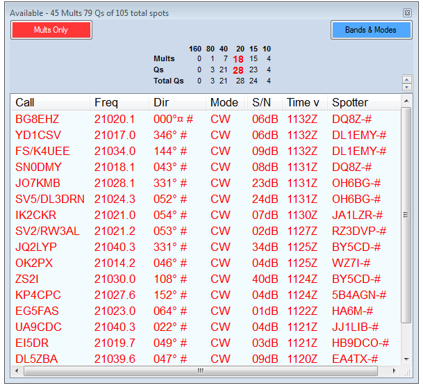
Before you ask – the Band Buttons in N1MM Logger Classic’s Available Mults & Qs window have moved to the Entry window in N1MM Logger+.
Key Features
- The Header – The header shows the number of Available Multipliers and QSO’s. (Example 4 Mults 12 Qs)
- The Summary Panel – the table in the center of the window header indicates how many new QSOs and new multipliers are currently available on each of the contest bands. The bands with the most multipliers and QSOs available is highlighted in red.
- The Mults/Mults&Qs Button – clicking this button toggles between showing both Qs and Mults and only Mults in the lower pane of the Window (also known as the Spots listbox). It is color-coded with standard N1MM coding for Mults and Qs to remind you of which is which at 3 AM on Sunday. Its color and caption always reflect your current choice, not the one that will be invoked when you click it.
- The Bands & Modes Button – Clicking this button opens a Bands/Modes menu which looks in general like the Bands/Modes tab of the Telnet window, but which only affects the contents of the lower pane of the Available window. Options which are not available in the current contest are greyed out.
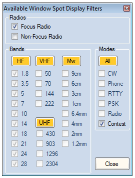
- If you check the Focus Radio box, the spots listbox will only display spots that are on the band to which the focus radio or VFO is set. If you change the focus to another radio or VFO, the spots listbox will switch to displaying only those spots. The non-focus radio or VFO selection is disabled when SO1V is selected
- If you check Contest under Modes, only those spots that fit the contest modes will be displayed in the Available window’s spots listbox.
Spot Listbox
The list box (the lower section of the window) shows spots received via Telnet. There are 7 columns, nominally in this order: Call, Frequency, Dir (bearing), Mode, SNR (Signal-to-noise ratio) for Skimmer spots, Time (hhmmZ) and Spotter.
- You can click and drag the column headings to any order you want, and narrow the window to reduce its size anf hide columns you don’t care about.
- You can size the columns by dragging the right edge of the column title. Columns that appear to be missing will show with a very light colored double bar. Grab the right side and drag.
- Clicking on a column title will sort the column, and clicking again will reverse the sort order.
- An indicator of split spots appears next to frequency.
- Spots coming from a local Skimmer are shown with a (!) to the right of the bearing, and those from a non-local Skimmer or the RBN (other than your spots, if you are a contributor) are tagged with with (#). A sunrise/sunset indicator is shown to the right of the bearing where applicable, as an aid to determining which spots may either be “perishable” or particularly suited to a gray-line QSO.
- Spots are colored by default as follows:
- Green – double multiplier
- Red – single multiplier
- Blue – valid QSO
The colors may be changed in Manage Skins, Colors and Fonts, on the Entry window’s Config menu.
Right-Click Menu
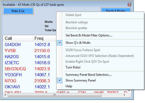
- Delete Spot – If you right-click on a spot in the spot listbox, the right-click menu will come up, and the “Delete spot” option will not be greyed out. Click it to delete the selected spot. Do not left-click the call first.
If your mouse has a clickable scroll wheel, you can also delete spots by clicking on the callsign with it
- Blacklist callsign/Blacklist spotter__ – Right-click on a spot, and click either option to get rid of either a persistent busted spot (e.g., EK3LR) or a problem spotter.
- Set Band & Mode Filter Options – Opens the same dialog as the Bands & Modes button on the window header.
- Show Qs & Mults – Replicates the toggling function of the Mults & Qs button on the window header.
- SO2R Focus Follows Spot – When enabled, when you click on a spot, and you are not currently transmitting, the Entry focus will move to the Entry Window of that spot.
- Advanced SO2V VFO Selection (Radio Dependent) – ((Single Operator Two VFO Operation (SO2V)|#Advanced_SO2V_for_Radios_with_Separate_Sub-Receivers|the chapter on SO2V operation)) for details. Works on radios with separate sub-receivers.
- Enable Right-click QSY on Spot – In SO2V and SO2R operation, QSYs the second VFO or radio to a spot when it is right-clicked, without changing the entry focus.
- Turn Rotor – turns the rotator for the Entry window that has the entry focus to the bearing for the station in the call-frame or call-sign textbox
- Summary Panel Band Selection – Allows you to customize the Summary Panel for any desired mix of HF, VHF and microwave bands.
- Show Summary Panel – uncheck this option to reduce the size of the Available window by hiding the Summary Panel
- Help – Internet connection required – displays this section of the manual
-7- The Info Window
The illustration below is a typical Info window with all options enabled in the right-click menu, also shown.
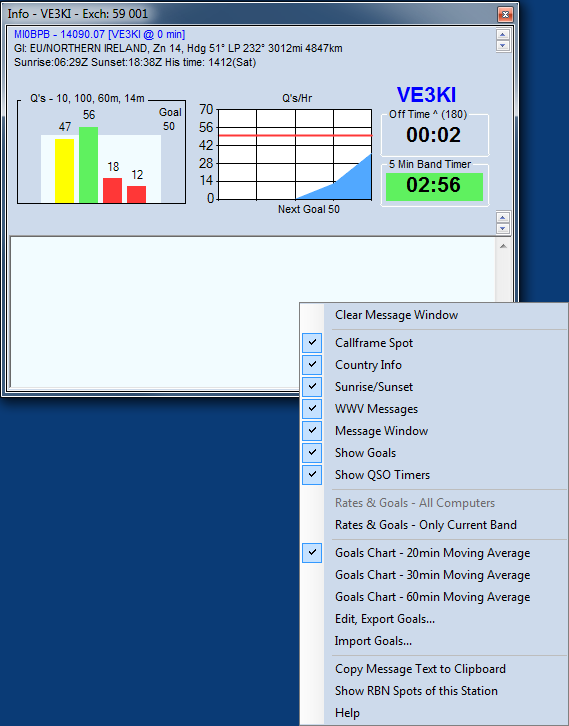
To open the Info window, select “Info” on the Window menu of the Entry window
Key Features
- The title bar shows the station call sign (from the Station Data table) and the default Sent Exchange for the current contest. The operator’s call sign is shown in blue on the right side of the window. If another operator signs on using Ctrl+O or the OPON text command, that cal lsign will replace the other.
- The sent exchange is shown in the title bar. The next QSO number will be shown on the title bar if it is a serial number contest. Example: Exch: 59 002
- The content of the window, other than the long-term and short-term rate displays, is selectable from the right-click menu.
- The first line is the spot that is in the call-frame of the Entry window, including any comment.
- The second line provides country information, including long and short-path headings, as well as short path distance to the country of the call-frame spot.
- The third line provides sunrise and sunset times in UTC at the DX location, plus his local time
- The fourth line displays the last WWV message received from the connected Telnet node. There were none when this screenshot was taken.
- Below the information lines are two graphs for rates and goals. The left-hand one shows near-term rates. Left to right, these are the rate for the last 10 QSOs, the last 100 QSOs, the last hour, and the interval since the start of the current clock hour. The right-hand graph displays hourly rates for five intervals, selected from the right-click menu to be either 20, 30 or 60-minute moving averages. Each vertical line represents one such interval – the rightmost edge is the current interval, which may not have been completed at any given moment
- The open area in the bottom part of the window is for messages from the program. One important use is for notification when you are spotted on the DX Cluster network, and by whom. It is also the place, in a multi-op, where the program reports any difference in entry category between computers on the network (multi-single versus multi-two, for example).
One of the right-click menu options (“Show RBN Spots of this Station”) opens a browser window displaying recent spots for the station call sign on the Reverse Beacon Network (RBN). This can be a useful indicator of whether and where your signal is being heard in CW and RTTY modes; it is of no use in phone contests.
Note that with the advent of the RBN, the sheer number of spots received and listed in the Available Window and on the Bandmaps within the spot timeout period may exceed the computer’s capacity to process them. The program monitors CPU utilization, and when it approaches a dangerous level, automatically trims a small number of the oldest spots. When this takes place, you will see an advisory message in this section of the window, so that you can decide if you wish to make any changes in your DX cluster filtering or other variables.
QSO Timers and Counters
The Info window also displays, under the current operator’s callsign, a number of useful indicators. These include:
– A timer to indicate off time for contests where there are minimum limits on off times, or to display the time elapsed since the last contact was made as a supplement to the goals charts. Right-clicking on the time in this box will open a pop-up menu in which you can choose what is displayed in this timer. The available options include:
- Display Off Time (full clock minutes with no QSO’s) – off time timer for rules compliance
- Current Interval Count Down Timer – counts down in hours and minutes from the beginning of the clock minute after the last QSO was logged, starting at the off time limit and counting down towards zero
- Current Interval Count Up Timer – counts up in hours and minutes from the clock minute after the last QSO was logged, starting at 0:00
- Cumulative Contest Off Time – adds the durations of off times that were long enough to qualify under the contest rules. If the current off time is not yet long enough to qualify, it is not included in the total. Note that the Start date and time for the contest in the Contest Setup dialog must be correct for the cumulative off time to be calculated correctly.
- Time Since Last QSO (not for off time rule compliance) – counts the minutes and seconds since the last QSO was logged
- All Computers Radios – the time since the last QSO was logged from any station in the network
- Both Radios (SO2R), VFO A/B (SO1V/2V) – the time since the last QSO was logged from this station
- Left Radio (SO2R), VFO A (SO2V) – the time since the last QSO was logged from the left/VFO A Entry window
- Right Radio (SO2R), VFO B (SO2V) – the time since the last QSO was logged from the right/VFO B Entry window
When an off time option is selected, the frame for this timer includes, besides the words “Off Time”, an arrow (^ or v) indicating whether the timer is counting up or down, and the minimum duration (in minutes) for off times for that contest and category. The timer is in hours and minutes; the background will change to light green once the minimum time has been reached.
– In some contests and entry categories, there is a second timer or counter display to help you comply with contest rules for band changes when there are band change time limits or counters. If there is a band change time limit, this timer counts down in minutes and seconds from the beginning of the clock minute after the first QSO logged on a new band. The band change timer does not start until the first band change of the contest. The background color changes to pale green once the required time limit has been reached and the counter has reached 0:00.
If the contest and category has a limit on the number of band changes per hour, instead of the second timer there is a band change counter. This band change counter has a “stop light” (red/yellow/green) colored background, to warn the operator when nearing or exceeding the allowed number of band changes in the current clock hour.
– There may also be a mult-run indicator that displays MULT or RUN in the Multi-One category or “1” or “2” in the Multi-Two category. The Multiplier or Run status for this station can be toggled with the key combination Ctrl+Alt+M.
Contest Goals
In N1MM Logger+, goals are stored in a table in the Admin database. Only one set of goals can be active at any time, and regardless of the contest you open, they remain active until replaced. However, if you have defined a goal file on the Associated Files tab for a given contest, that goal file will be loaded whenever you start a new instance of that contest. For example if you define CQWW goals.txt as an Associated File in one instance of CQWWCW, that goal file will be loaded any time you open any instance of that contest.
Here are some other key things to remember about N1MM Logger+ goals:
Editing and Exporting Goals
Right-click in the Info window, and click on Edit and Export Goals. That opens the following dialog:
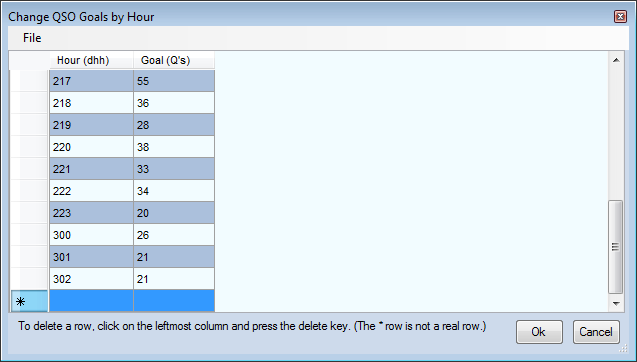
You’ll note that the hour is stored in the form “dhh” where “d” is __the day of the contest and “hh” is the beginning of the hour, in clock time, not in terms of the hour in the contest. Hence, for example, “222” denotes the second day of the contest and the hour beginning at 2200Z. In the example, the goals were derived from an ARRL November Sweepstakes, which runs until 0300Z on the third day.
You can edit this table just as you would any other table in an N1MM Logger+ database. Be careful with the “hour” column until you are comfortable with the convention. When you have made your changes, you can either export to a goals file in text format, which will be placed in Documents\N1MMLogger+\GoalFiles, or simply OK out of the dialog, in which case the changes are saved to the Admin database’s Goals table.
Goal Files
This is the Goal file format:
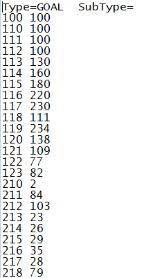
You can create a Goal file with a text editor and import it into the database using the Import Goals function (see below). Be sure that you use a straight text editor for this, such as Notepad. Word processing programs can insert special codes that N1MM+ does not understand.
Note that you do not need to enter anything for those hours when you do not plan to operate, but you do need the header just as it appears here.
Set Your Start Time
Be sure to set the contest start time (in the Contest Setup dialog) to the correct value for any contest in which you intend to use goals. As you can imagine, this is important to ensure that the appropriate goal is displayed for the appropriate hour of the contest.
Importing Goals
Click on Import Goals, and this submenu will appear. You can import goals from a prior contest log or a .txt file in the GoalFiles Document directory
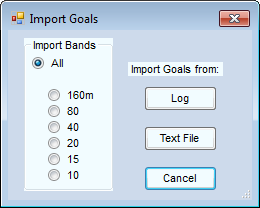
- Typically, you will want to import goals from all bands, but if you plan to enter a contest single-band, you can set goals for that band only by clicking the appropriate radio button.
- Click on the “Text File” button, and a dialog opens showing you all the goal files in the GoalFiles document folder. Select one, open it, and the contents are transferred to the database.
- Click on “Log” and something new happens. This window opens:
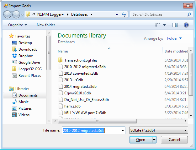
Select the database you want to get your goals from, and click “Open”.
Now this dialog opens:
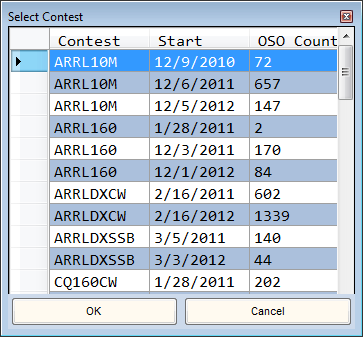
Select the contest from which you want to derive your new goals, and OK out. Once imported you can edit the goals as outlined above, and optionally export them to a Goals file.
Importing Goals (Developer notes for manual editors)
For the goal import files:
- All import blank lines are ignored.
- All import lines beginning with a # in the first character position is considered a comment line and is ignored.
- The Goals hour is defined as the hour of the day, not the hour of the contest. This is to make it easy to align goals with GMT time when the contest doesn’t start at 00:00gmt.
- Before the contest start, the Goals will be set to the contest first hour goal.
- The Goals are set to zero if Info window charts display 96 hours after the start of the contest.
- If the user Right Clicks on a QSO in the Log Window and selects the option to display Rates & Goals in the Info Window, the Charts will update with the Goals as if it occurred during the contest.
- If the database doesn’t contain goals, a default goal of 50 is used.
- If an error occurs during the selecting the goal, a a goal of 50 is used.
- File formats accepted:
- The View, Statistics text file (*.TXT or *.txt) can be used as a goal import file. All bands or one band can be selected during import. Opened in an editor it has this format:
     Day        Hr  1.8   3.5     7   14   21   28   Tot  Accum
     2010-11-27 00    0    70   146    5    0    0   221    221
     2010-11-27 01    0   116   119    0    0    0   235    456
     2010-11-27 02   71    27   128    0    0    0   226    682
     Total       0  306   867  2088 2156 1763  542  7722   7722
- The Goals import file can be a .TXT or *.txt file hand generated space(s) or tab delimited, repeated spaces or tabs are OK. Examples are:
0  100
1  111
2  222
- The Goals import file can be a *.CSV or *.csv hand generated file, comma separated, repeated spaces or tabs are OK, only one comma in the line is allowed
0, 1001, 1112, 222
- The Goals import can also be the *.TXT file exported from Edit, Goals window.
Type=GOAL  SubType=
     100     350
     101     337
     102     321
-8- The Score Window
The Score window is automatically formatted to display the components of the score (such as QSOs, zones, and country multipliers) in the current contest.
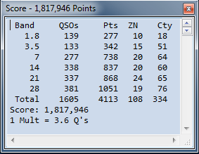
The Score window has an independent font resizer – the up/down arrows in the upper right corner – and is now resizeable. If you reduce its size so that not all the contents can be seen on-screen at once, scroll bars will appear to allow you tosee parts of interest without re-sizing.
With a right mouse click, a menu will appear
- Copy all – Copy all info to the Windows Clipboard.
- Print to file – Print the score summary to a file.
- Help – Show the user manual section for this window (Internet required).
-9- The Multipliers Window
The Multipliers window is opened from the Entry window’s Window menu. Right-clicking on the “Multipliers” selection opens a sub-menu from which you can choose one of five multiplier displays, depending on the contest.
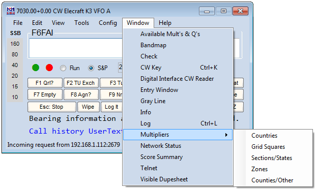
Choosing Countries, in a CQWW log, displays a chart like this:
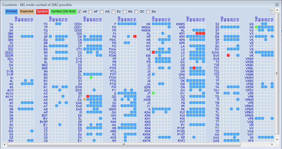
If your Multipliers window is empty or incomplete, right-click and look on the right-click menu for the option “Show Only Worked & Expected to be Worked Mults.” If it is checked, then The multiplier window will only show mults that have been worked, ones that you have included in an expected mult list, and mults that have been spotted. Uncheck it, and the Multipliers window will show all possible spots, worked or not.
Key Features
The drop-down menu gives 5 choices, each of which is tailored to meet needs in certain contests. Whichever you pick, there are some key common features.
Color-Coding
The color blocks displayed are, by default, blue for a band where the mult has already been worked (but a valid QSO is available), red meaning that a station is available for a single multiplier on that band, and green meaning a double multiplier QSO is available on that band, in those contests that have them. These colors may be changed to meet special needs through the Manage Skins, Colors, and Fonts editor on the Config menu of the entry window.
Decisions by the program about whether a multiplier is available on a given band are based on callsigns, and for those contests in which multipliers are determined by the content of the exchange, the color-coding may not be accurate. A multiplier block remains on the chart until the underlying spot has expired under the current bandmap spot timeout setting. Open a Bandmap along with the Multipliers window, set a short timeout, and you will be able to see this happen.
Tailoring Mult Lists for Particular Contests
Users will often want to tailor one of the five available multiplier lists to a particular contest or QSO Party; for example, in WAE, non-European competitors will only want to keep track of European country multipliers.
As a first step in this direction, the seven check boxes across the top right of the window permit you to limit the display to a single continent. Only one can be displayed at a time, but once you leave the “All” display, you will discover that you have some flexibility in the way that the columns of multipliers are arranged, to help you make best use of your screen space. This varies from one type of multiplier to another – for example, the States/Sections window must be displayed as a wide rectangle to group 10 US call areas and the Canadian sections in logical order.
Gerald, VE1DT has done considerable work on defining the other tailoring possibilities, and much of what follows is based on his efforts.
Options for doing this are found in the right-click menu reached from any of the five multiplier lists.
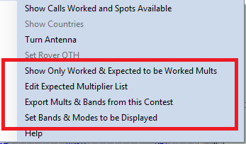
Show Only Worked & Expected to Be Worked Mults – Checking this option limits the mults displayed to those specified by one of the methods below.
Edit Expected Multiplier List – Clicking this option opens the following dialog
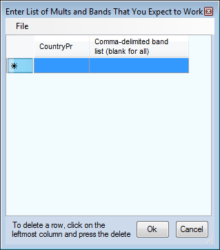
You can use this dialog to edit the list of expected multipliers, one at a time. For example, if you are editing the countries to be displayed, you’ll need to enter the country prefixes one line at a time, in upper case exactly as they are shown in the Multipliers window. For example, you need to enter “CE0X” not “CE0/X”. If you enter specific bands, note that they are specified by frequency in MHz, not by wavelength in meters. Here’s a simple example:
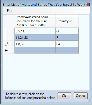
Click OK to save the list, and if you check the “Show Only” option described above, the Multiplier window will look like this:
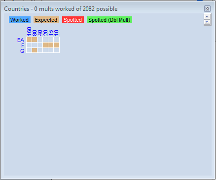
Similarly-limited multiplier displays can be generated by the same process in the Zones display. Before the “Show Only” option is checked, this display may look like this:
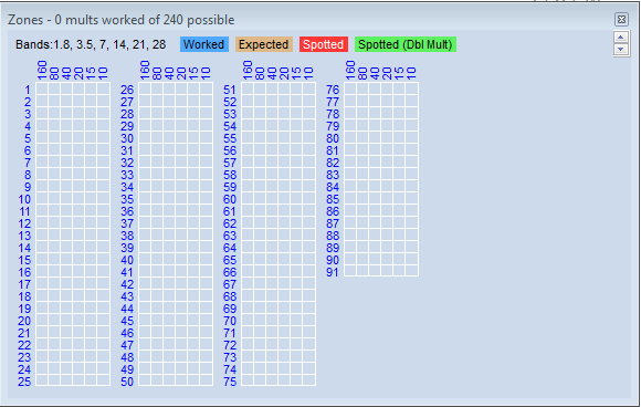
The reason for the 91 zone lines in this example is to cover both CQ and ITU zones. In the CQWW contests, the display will only show the 40 CQ zones. In the ITU list, zones 76-91 are sea zones and you may wish to eliminate them from the display.
- Hand editing – you can use the Edit Expected Multiplier List dialog to enter each of the 75 land zones and list all six bands for each zone, in order to limit the display to only those 75 zones. After creating the list, you can use the File > Export menu item in the edit window to export the list to a file.
- Create a list of the zone/band combinations worked in the current log using the Export Mults & Bands from this Contest menu item. This will create a file of those combinations that appear in the log, which can later be imported using the next method.
- Imported file – after having created a file by either of the first two methods, you can use the File > Import menu item in the Edit Expected Multiplier List dialog to import the list. The list is a simple text file, so you can use a text editor instead of the edit window to make changes before importing the file.
Mouse-over
Mousing over any prefix will display information about it – the name of the country, its continent and zone, long and short-path bearings, and the distance
Resizing
The Multipliers window may be reduced in size, in case your screen real-estate is too limited to show the whole thing. If you shrink it right-to-left or left-to-right, a horizontal scroll bar will appear to remind you that there is more information to be seen. Vertically, down-sizing causes the chart to be rearranged, so that a vertical scroll-bar is not necessary.
Clicking on Multipliers
Left-clicking on a block that is colored to denote either a single or double multiplier will QSY VFOA or Radio A to the frequency of the station that you can work for that multiplier. Blocks denoting stations that would be valid QSOs but not multipliers are not clickable.
- The program will first look for multipliers that match on this band. If their are no mults that match on this band, then it will look on all band for the latest mult spotted.
- The program searches through all spots regardless of the filter settings for the mult window. If, for example, you do not want to jump to SSB spots in a cw contest, filter out those spots using the Telnet window filters. You might want to move a SSB station however, so consider that possibility.
Right-clicking on a multiplier block or elsewhere in the open Multipliers window (other than the title bar)opens the right-click menu.
Right-Click Menu – multiplier-specific options
- Some of the options are keyed to the particular multiplier block clicked, and will be greyed out if you click elsewhere. To Show Calls Worked and Spots Available, you will need to right-click one of the band blocks, not the prefix.
- Show Calls Worked and Spots Available will display a list of all stations already worked for the multiplier, regardless of band, whether the box you clicked is green, blue, red or empty. It will also display a list of spots currently available for the multiplier on a new band or mode.
- If you are showing a chart of zones worked (in CQWW, for example), this option can be clicked to show the country prefixes that count for the zone on which you right-clicked.
- Turn Antenna – if rotator control is enabled, clicking on this option will turn the antenna to the short-path direction of the multiplier from your QTH.
Other Right-Click Options
- Set Bands and Modes to be Displayed – opens a dialog that looks very much like the Telnet and Available windows’ Bands and Modes dialogs. The purpose of this option is to control the boxes that appear beside each multiplier. For example, you might use it to eliminate the boxes for a band(s) for which you do not have an antenna, or to limit the display to only a single box for the band of a single-band entry. Note that this operates on the display boxes, not on the spots themselves. In a contest in which there are no per-band multipliers (e.g. ARRL Sweepstakes or ARRL RTTY), and in which there is only one box per multiplier, using this option will have no effect on which multipliers are spotted and displayed.
- Help – will take you via the Internet to this section of the manual.
Move Multipliers Window
- Move Multipliers – The Move Multipliers link on the Window menu of the entry Window will display this window. For every call sign in the spot table and every band/mode selected using the Select Band & Mode button, displays the multiplier status of that call sign and indicates with background shading which band that station was spotted on. The multiplier status depends on the program’s ability to determine the multiplier status solely from the spot information. It is not updated when a contact is logged, deleted, or spotted, but only when the Refresh button is used. A left-click on a call sign will QSY the radio to the first spotted band. If a station is spotted multiple times, repeated clicks will QSY to the next spot on the line. In SO2R or SO2V, if a radio or VFO is already on the spot band, that radio/VFO will be used, otherwise the active focus radio will be used, or Shift+Click will QSY the other radio. A mouse wheel click will delete the line.
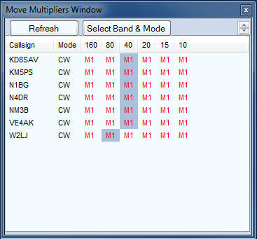
-10- The Statistics Window
The Statistics window can be found under View > Statistics in the Entry Window. New in N1MM Logger+ is provision of graphical as well as tabular presentation of data. Select either by clicking the tabs at the top of the screen.
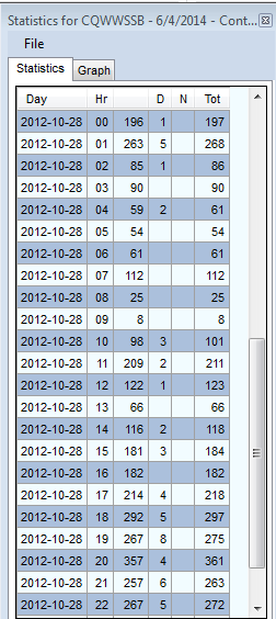
Or you can present the same data in graphical form. Be forewarned, this is not a PJ2T log – that call is just an example.
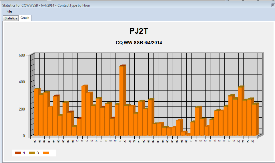
The graphical representation really comes into its own when the data are more complex. For example, if you want to know at a glance which bands were most productive when, graph hours versus bands.
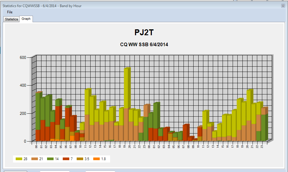
During a contest, if you are checking Statistics and a station comes back, just start typing. The statistics window will go to the background and every typed characters will go to the Entry window.
General
The Statistics window allows you to select almost all database fields from a contest for display in tabular form by row and column, or in graphical form. The following table explores the options and their usefulness in various contexts.
[table “” not found /]Old contests may not have valid values in fields that have been added since the contact was logged. The number of contacts shown on screen and printed on the summary sheet are without dupe contacts.
File Menu
- Copy All – Copy the contents of the window to the Clipboard, either as text or as a graphic
- Print – Print the statistics table to a printer. Font can be set by user. Also prints graph displays if supported by your printer
- Print to File – Print the statistics table to a file. This function is greyed out when a graph is being displayed.
Example Statistics
Try these examples with an old log:
[table “” not found /]-11- The Skins Colors and Fonts Window
The configuration settings for N1MM Logger Plus allow customization of most of the fonts and colors used in the program. To access the Manage Skins, colors and Fonts dialog window, select Manage Skins, Colors and Fonts on the Entry window’s Config menu.
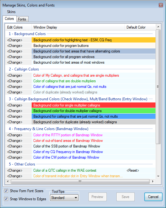
Colors Tab
The Colors tab displays the current setting for 24 program colors. Clicking the <Change> button in the left column allows you to select a different color. If you select a color different than the default skin color (read about the default color below), a <Reset> button will appear in the right hand. Clicking <Reset> will revert that color to the program’s default value, regardless of the skin you are currently using.
Color settings can be grouped in three categories: Global, Shared, and Dedicated.
- Global color settings affect every window in the program. Examples of Global colors are:
- Background color for all program windows
- Background color for program buttons
- Background color for text areas of most windows
- Shared color settings affect several windows in the program. Examples of Shared colors are:
- Callsign colors (dupes, normal Qs, mults, double mults): Affect the colors of callsigns in the Bandmap, the Digital Interface Receive window, and the Entry Window callsign field
- In an example of extended sharing, in the Function Key Editor, Comment lines are identified by using the callsign Dupe color, Run Message lines are the normal QSO color, and S&P Message lines are the Double Mult color.
- Callsign background colors (dupes, normal Qs, mults, double mults): control background colors in the Check window and the Entry window Band Panel buttons.
- Callsign colors (dupes, normal Qs, mults, double mults): Affect the colors of callsigns in the Bandmap, the Digital Interface Receive window, and the Entry Window callsign field
- Dedicated colors affect only one window. Examples of Dedicated colors are:
- Frequency and line colors only affect the Bandmap(s)
- Background color, color of normal text, and Color of My Callsign all apply only to the DI Receive window
- Color of transmit indicator dot in the Entry Window – the color the normally red dot turns to when transmitting
Fonts Tab
The Fonts tab displays the current setting for five program fonts. Clicking on the font description allows you to select the font family and default font size. If the selected font family and size are different than the default program font (read about the default font below), a <Reset> button will appear to the right of the font description. Pressing <Reset> will revert that font to the program’s default value, regardless of the skin you are currently using.
When making large changes to font sizes, some windows may not automatically adjust to the new sizes. It might be necessary to close and re-open the windows for the new size to display properly.
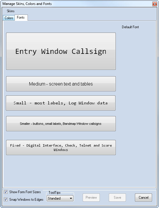
- Entry Window Callsign
Controls the font family and size for the Entry Window fields – callsign, signal report and contest exchange
- Medium – Screen Text and Tables
Controls the font family and size of warnings and special messages in the Entry, Info, and Multipliers windows
- Small – most labels, Log and Network Status Window data
Controls the font family and size for notes in the lower portion of the Info Window and the grids of the Log and Network Status Windows
- Smaller – Buttons, Small Labels, Bandmap Window Callsigns
Controls the font family and size for all program buttons and tabs, notes in the upper portion of the Info Window, summary table in the Available Mults and Qs Window, frequency and callsigns in the Bandmap, text in the Multiplier Window. This font is used in every window of the program.
- Fixed – Digital Interface, Telnet and Score Windows
Controls the font family and size for the Check Window, Telnet Window, Digital Interface Receive Window and the Score Summary Window.
Most windows have a “Font Sizer” in the upper right-hand corner. You can use this control to adjust the font of a particular window to be larger or smaller than the default. This control only changes the main font of the window. See Show Form Font Sizers below.
The Skins Menu
Click the link at upper left.
Load Existing Skin
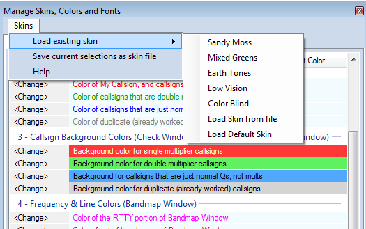
Skins are collections of settings that include the font family, font size, and colors. N1MM Plus includes a variety of built-in skins (see screenshot) from which you can choose. You cannot change these built-in skins, but you can use them as a foundation in creating customized skins.
Load Skin from File
Loads font and color settings from a .SKIN file. The files must be located in your Documents\N1MM Logger+\SkinsAndLayouts directory.
Load Default Skin
Self-explanatory. Gets you back to the default set of colors and fonts.
Save Current Selections as Skin File
After adjusting colors and fonts, you can save the settings in a .SKIN file, which will be stored in your My Documents\N1MM Logger+\SkinsAndLayouts directory.
Saving Your Skin
From a process perspective, you do not make Skin Changes. You make Font and Color changes. Begin by loading a skin that resembles what you want. Then make changes to Fonts and Colors. When you settle upon a combination that you like, select >Skins >Save current selection as a skin file.
Pressing the >Save button after making changes to Fonts and Colors will preserve the changes you have made, but does not write those changes to a skin file. The original skin file from which you started is unaffected unless you overwrite it with >Save current selection as a skin file.
Other Settings
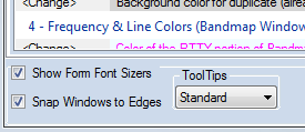
These are found in the lower frame of the dialog, and displayed along with any of the tabs
Show Form Font Sizers
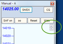
Enabling this setting allows individual font sizes in specific windows, regardless of the default font size setting. When enabled, Font Sizer controls will appear in the upper right-hand corner of the following windows: Telnet, Log, Available Mults & Qs, Multiplier, Digital Interface, Info, Check, Score Summary, and Bandmap.
Snap Windows to Edges
Enabling this setting simplifies the task of aligning program windows adjacent to each other.
Tooltips
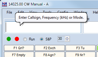
Tooltips display helpful hints that appear when you pause your mouse over certain locations in program windows. The option at the bottom of the Skins, Colors and Fonts window allows you to choose between no tooltips (once you feel comfortable with the program), “standard” tooltips (usually one line of text) and “balloon” tooltips that may be several lines. You’ll find tooltips particularly useful in the Bandmap and Available Mults and Qs windows, where mousing over a call-sign displays the age of the spot, who spotted it, how long ago, and anything that was in the Comment field of the spot.
Changing Font Size and Color in Windows’ Title Bars
From Tom, N1MM – 2017-04-05
N1MM+ users have posted questions and submitted feature requests to change the appearance of the title bars in the application. Unfortunately, that is not something that Microsoft puts under application control. There are two things I found that you can do to improve the appearance of the title bars.
- This is the important one. Go to Display Settings/Advanced Display Settings/Advanced sizing of text and other items/Title bars and set the text size & bold attribute that you like. The bigger the text, the more legible it will be (especially if bold), but the more space every window on your computer will take up.
- To change the background color of the *inactive* windows, go to https://www.tenforums.com/tutorials/32118-change-color-inactive-title-bar-windows-10-a.html to learn how to do it. You have to edit the registry, and be pretty facile with hex/decimal manipulation to be successful at this one. Not recommended for most users. Again, this affects all the windows on the system. I chose to make my idle title bars the same color as the main window color in the skin that I use. Note that the color order is BGR, *not* RGB.
-12- The Visible Dupesheet Window
Example Visible Dupesheet
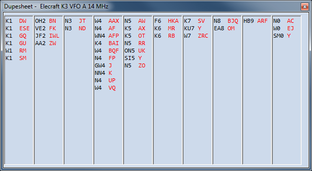
The Visible Dupesheet is a quick way to determine if a station is a dupe without having to enter the callsign in the program. The calls already worked will be indexed much like a paper dupesheet that is organized by call area and suffix. The Visible Dupesheet is especially useful for short, high speed contests like the NA Sprint. It is closely patterned on the Visible Dupesheet used by TR Log.
- Each VFO/Radio/Bandmap has its own Visible Dupesheet. The VFO/Radio A sheet displays all of the contacts for the band VFO/Radio A is on. VFO/Radio B does the same for whatever your VFO B/Radio is set to even if you don’t (or cannot) use VFO B
- The columns signify call areas. If a call area exceeds the number of calls that will fit it will overlap into an adjacent column with some dash lines to differentiate
- Each call area is sorted by suffix
- To see the dupe sheet for any band, set your radio to that band
- To check for a dupe, first look for the call area column, then look up the suffix, then the prefix
- If you don’t want both windows open, close one, position the other where you want it and then use Tools > Save Window Positions. The next time you start the program only one window will open
- Unless you can copy RTTY in your head, you do not need the Visible Dupesheet for RTTY contests. Obviously RTTY calls will tell you they are dupes or not as soon as they print
- The Visible Dupesheet can hold a maximum of 800 stations per band. Going above this limit will give a warning . Depending on computer speed and configuration, users may experience noticeable delays when using the Visible Dupe Sheet with logs containing more than 300 calls. Performance with 600 callsigns is acceptable with a 2.6 GHz computer running only Logger
- Font size is set here. The Visible Dupesheet uses the last (Fixed) font.
- There are no menus in this dialog
What is the Usefulness of the Visible Dupesheet?
By Steve, N2IC
First, let me say what this feature is not: It is NOT intended to be a step towards paper (or electronic) dupe sheet submission. A paper dupe sheet is an obsolete artifact of the pre-computer logging era.
Now, I’ll be perfectly honest about the utility of the Visible Dupesheet. I have been a user of TRLog for many years, as well as a fan of the NA Sprint contest. To do very well in an extremely fast-paced contest, like the NA Sprint, you have to minimize the amount of non-productive time. Any time you are not actually making a QSO is non-productive time. As you tune around a band, looking for new stations to work, you need a really fast way to determine if a station that you hear is a dupe. The fastest way to do this is to use only your brain. Some contesters have an amazing ability to keep their dupesheet completely “in their head”. For the rest of us, we typically reach for the keyboard and type the call into the entry window. As soon as you do this, N1MM Logger+ instantly tells you whether it’s a dupe. Excellent. However, some of the NA Sprint operators who use TRLog have found an even faster way to check for a dupe – using TRLog’s Visible Dupesheet feature. As you tune the band, you keep your eyes focused on the Visible Dupesheet. It becomes second nature to scan the Visible Dupesheet. When you hear a non-dupe that you want to call, you don’t even have to enter the call in the Entry Window, yet. Just hit the Enter key. If he/she comes back to you, you now have time to enter his/her call and exchange.
Obviously, in a contest where you work many, many stations on each band, this feature won’t work – it takes too long to scan the Visible Dupesheet when it is crowded with calls. However, this is not the case with the NA Sprint. The winners work no more than 150 stations per band, making the Visible Dupesheet an ideal way to dupe check.
-13- The Grayline Window
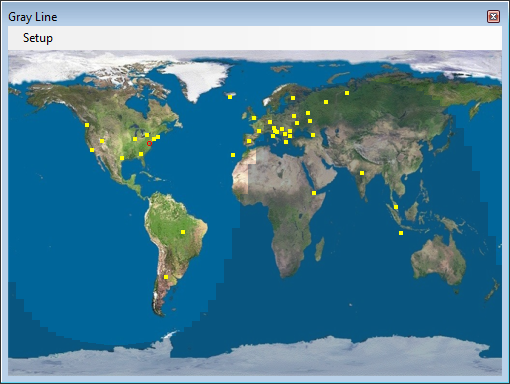
Setup Menu Selections
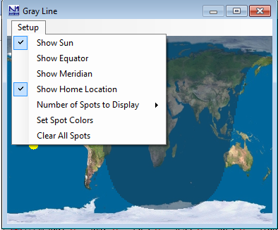
- Show Sun – Select or de-select showing the current position of the sun on the Grayline map
- Show Equator – Show or hide the Equator on the map
- Show Meridian – Show or hide the Greenwich Meridian
- Show Home Location – Will show a red dot on your location as set in N1MM+ and explained in Installing the Software.
- Number of Spots to Display – Select 0, 50, 100, 150 or 200 most recent spots to be displayed on the map.
- Clear All Spots – self-explanatory
-14- The CW Reader Window
The Logger’s CW Reader is receive-only. The CW reader engine cannot be used to transmit CW; to transmit CW, you must configure some other method in the Logger (serial or parallel port keying, or a Winkeyer, for example).
CW Reader Setup
The first time you open the CW Reader window, or any time the window is opened with no CW reader engine selected in the setup, the following dialog will be displayed:
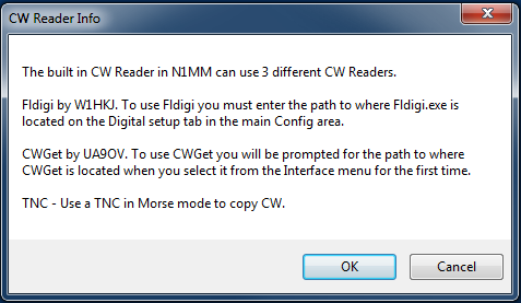
After clicking on OK in the above window, or at any time thereafter by selecting the Setup menu in the main CW Reader window, the following setup window will be displayed:
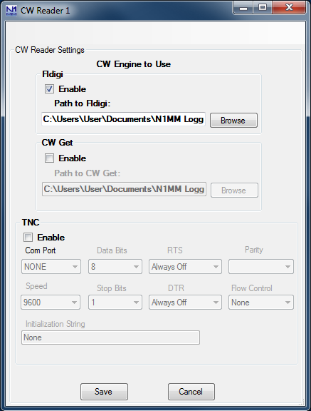
N1MM Logger+ supports three different CW reader programs, or “engines”.
The first, Fldigi by W1HKJ, is also one of the digital engines that is supported by the Logger for digital modes. Fldigi is not automatically installed with N1MM Logger+; if you want to use it, you must download and install it. Once fldigi has been downloaded (and optionally configured for digital mode operation – see the Digital – Fldigi for Sound Card Modes chapter), it can also be used as a receive-only CW reader (N1MM Logger+ does not support transmitting CW from fldigi). Click on the Enable check box for Fldigi. You may wish to use a separate copy of fldigi for CW from the digital modes copy; that way, the configuration setups for fldigi for CW and for digital modes can be saved separately. If you do this, both of these copies of fldigi should be outside the Program Files or Program Files(x86) paths in Windows Vista or later, in order to enable the configuration files to be saved. Although you can run fldigi stand-alone from a location in the Program Files path, any copy of fldigi that is run from N1MM Logger+ in Windows Vista or newer must not be located in a protected Program Files path. You do not need to do the original installation of fldigi outside the Program Files path. Simply install in the default location, create a new location outside the Program Files path, and copy the fldigi.exe file from the original installed location into the new location. The first time it is run from the Logger, fldigi will create the other files it needs in the new location.
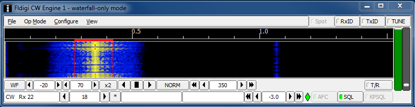
The second supported CW reader program is CwGet by UA9OV. This is a shareware program that can be downloaded from the www.dxsoft.com web site. It may be used either unregistered (free), or registered (requires a fee to be paid to the author). The unregistered version does not save configuration information between runs, which means that you will have to perform the setup (primarily selection of the sound card to be used) each time the CwGet engine is started. In either case, after downloading and installing CwGet you can select it in the CW Reader setup window by checking the Enable check box for CW Get and entering the path to the program. It is also possible to select command line settings for CwGet in the setup window. Unlike fldigi, CwGet may be run from the default installation location even if that location is in C:\Program Files or C:\Program Files(x86). You do not need to make a separate copy of CwGet outside the Program Files path.
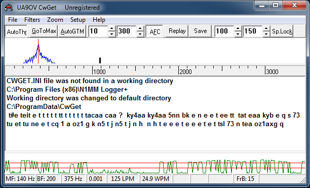
The third supported CW reader type is an external TNC that is capable of decoding Morse code. You set up the COM port communications parameters for the TNC in the bottom part of the window.
Once the CW reader engine has been selected, click on Save to save the selection and exit the Setup window. This will open one or two new windows: the CW reader engine window (if you are using fldigi or CwGet) and the CW Reader text window (see next section). There will be further configuration required in the CW reader engine window the first time it is used (or every time if you are using an unregistered copy of CwGet), in order to select the sound card that is used for decoding. The fldigi configuration window may open the first time you use it; if it does, the only configuration information that is needed for the CW Reader engine is the sound card setup, and you can skip over the other parts of the configuration. The first time fldigi is used as a CW reader engine, it may start up in a digital mode and you may need to change its operating mode to CW.
Since N1MM Logger+ supports two Entry windows (for two VFOs in SO2V, or for two radios in SO2R), it also supports two CW Reader windows. The CW Reader window corresponding to each Entry window is opened from the Window > CW Reader menu item in that Entry window. In order to save separate configurations for the fldigi engines in the two CW Reader windows, you will need to use two separate copies of fldigi, one for each CW Reader window. If you want to use CwGet in both Entry windows, it should be a registered copy.
Both CW Reader software engines (fldigi and CwGet) use a sound card for decoding. This requires an audio cable connection between the radio and a sound card input. The radio output can from a speaker or headphone output, or a line output if a separate output (possibly labelled for digital modes) is available. The sound card can be a motherboard sound card or a separate sound card, either internal or external. If possible, the input used should be a line-level input. If the only input available is a microphone input, you may need to supply an attenuator (resistive voltage divider) between the high-level output from the radio and the low-level microphone input on the sound card. In Windows 10, starting with the Spring 2018 update, you may need to adjust a Windows privacy setting (Windows Settings > Privacy > Microphone) called “Let apps use my microphone”. This option must be turned On to give programs like the CW Reader software engines access to sound card inputs.
If you are using a TNC as the CW Reader engine, the audio connections will be between the radio and the TNC, and there will be a serial port connection between the TNC and the computer.
Note that older versions of fldigi only use the left channel on input; for that reason, in most SO2V installations these older versions of fldigi can only be used from Entry Window 1. Starting with fldigi version 3.22.06, fldigi is now capable of using either sound card channel for input. In any copy of fldigi that you want to use with the right channel of the sound card, use the Configure > Sound Card menu item in the fldigi window to open the fldigi configuration window. Select the Right channel tab, and near the bottom under Receive Usage, check the Reverse Left/Right channels check box to switch fldigi to use the right channel on receive. Click on Save to save the configuration change, and then close the configuration window.
Recent versions of fldigi may default to requiring confirmation from the user before you shut them down. If that shutdown is initiated by shutting down N1MM Logger+, instead of by shutting down the CW Reader window and engine first, this can result in fldigi continuing to run after the Logger has shut down. This can cause problems the next time you start up the Logger. To prevent this from happening, you need to make a change in the fldigi configuration file. In each folder that fldigi is run from, find the file called fldigi_def.xml. (Note: this file is created the first time fldigi is run from this location, i.e. it will not exist until after you have run that copy of fldigi at least once). Right-click on the file name, select Open with… and then select Notepad or WordPad as the program to open the file with. Look for a line that reads <CONFIRMEXIT>0</CONFIRMEXIT> or <CONFIRMEXIT>1</CONFIRMEXIT>. If you see a 1 between the two keywords, change it to a 0 and save the file. Repeat this for every copy of fldigi you use from within N1MM Logger+ (CW Reader 1, CW Reader 2, DI1, DI2, and any digital RX-only windows you use fldigi in).
If you choose to use CwGet as the engine, note that if you use an unregistered copy of CwGet with input from the right channel of the sound card, that unregistered copy will not transfer decoded text to the corresponding CW Reader window. In most SO2V installations CwGet will have to be registered if you want to use it from Entry Window 2. Also, unregistered copies of CwGet will not save their configuration data, meaning you will have to set up the sound card parameters every time you start CwGet; registered copies will save their configuration data and remember it between sessions. The configuration data is stored in an ini file in the N1MM Logger+ user files area (the same location as the N1MM Logger.ini file). It will be called CWGET1.INI (Entry Window 1) or CWGET2.INI (Entry Window 2 in SO2R or SO2V).
CW Reader Operation
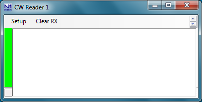
The CW Reader window is where decoded received text appears. If the scrolling method selected in the Digital Interface Setup window is “scrolling”, then as new incoming text is decoded, older text is scrolled off the top of the screen. If the scrolling method selected for the Digital Interface is “non-scrolling”, then text does not move, but incoming text overwrites previous text on the current line; the current line where incoming text is displayed is indicated by underlining, and moves down the window one line at a time, jumping back to the top of the window once the bottom line is filled. You can stop scrolling temporarily by clicking on the green bar at the left of the window; the green bar will turn yellow and the text will stop scrolling so you can copy it without having to follow it up the screen or catch it before new incoming text overwrites it. When you click on the yellow bar to resume normal scrolling, the bar will turn green, text that was decoded while scrolling was stopped will be sent to the window, and then normal operation will resume.
You can click on call signs and exchanges in the text window; depending on where the focus is in the Entry window, this will automatically transfer the text that was clicked on into the call sign or exchange box in the Entry window. This operation is similar to the way the Digital Interface window is used in RTTY and PSK31.
There are two menu items in the CW Reader window. The first one, Setup, opens the setup window to enable you to change the CW reader engine. The second one, Clear RX, simply clears the received text window.
In order for the CW reader engine to work, the signal you wish to copy must be tuned in correctly. The CW reader engine has tuning aids (either a waterfall or a spectrum display in Fldigi, and a spectrum display in CwGet) to help you tune signals accurately. You can fine tune by clicking in the spectrum display, but be aware that fine tuning in the CW reader engine will have no effect on your transmitted signal’s frequency. If you wish to transmit on the same frequency as you are receiving on, your best bet is to set the CW reader engine’s audio frequency to be the same as your transmitter’s sidetone frequency, and then tune signals using the transceiver’s tuning knob (not by clicking in the spectrum display or waterfall).
Software decoding of CW (Morse code) has its limitations. The signal to be copied must be fairly strong (at normal CW speeds, the human ear can decode CW at lower signal-to-noise ratios than software can) and clear of QRM and QRN (heavy QRM or QRN can render the CW undecodeable). The sent CW timing must also be accurate (e.g. machine-sent CW). On a good machine-sent signal such as ARRL CW bulletins, software copy can be nearly perfect. On the other hand, sloppy hand-keyed CW can result in errors ranging from poor spacing (v e 3 k i instead of ve3ki) to a complete failure to copy (nothing but Es and Ts displayed, as the reader software triggers on individual dits and dahs).
-15- The Network Status Window
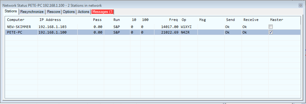
The N1MM+ network scheme also simplifies and automates the network setup. So long as each computer on the network is running in the same subnet, with the same version of N1MM Logger, and the same contest and multi-operator class in the Contest Setup, the network will be set up automatically.
If you open the Network Status window without enabling networking, you will see a framed warning: “Networked Computer Mode is off – Click here to turn on.” Do as it says (actually, click anywhere in the main body of the window), and the other computer(s) in the network will appear. If you turn on networking by accident with no other computers in the network, you can turn it back off using the “Stop Networking” button under the “Actions” tab.[\alert]
Tabs
Whenever you open the Network Status window, it comes up in the Stations tab.
The Stations Tab
As you can see above, this tab contains all the basic information about each station in the network:
- Computer – This is the name assigned to the computer in Windows
- IP Address – on the local area network
- Pass – The pass frequency (to which other stations on the network can pass new mults). Each station can set or change this frequency for itself manually (on the Actions tab) and all stations can then see the new frequency.
- Run – Whether each station is in Run or S&P mode
- 10/100 – What its current QSO rate is (last 10 and last 100 QSOs)
- Freq – What frequency it is currently on.
- Op – Who is operating (as set by OPON or Ctrl+O)
- Msg – What, if anything, that station has just done, such as pressing a function key
- Send/Receive – normally reads “OK” unless there is a problem with the network.
- Master – Permits checking to select one station on the network as the master. Check one to determine which connects to the Internet for cluster spots and time synchronization.
- Band – Note that if you sort on band, you will also sort on Run/S&P as the secondary sort. This may be useful for very large multi-ops where the station name does not indicate the band.
A (((*))) in the title bar of the Network Status window means that your computer just broadcasted its IP address, usually in the process of establishing a connection to the network. When connection is established, the title bar will reflect the number of stations in the network.
The red highlight on the Messages tab means that there is a network message waiting there that has not yet been read. In most cases, it is normal administrative traffic, such as a connect request from another station on the network. The red highlight may also be seen on the computer name during the connection process, usually accompanied by a red highlight in the Send or Receive column. These will disappear when a good connection is established.
In order to keep all of the clocks on a network in sync, all “slaves” – computers other than the one designated as “master” – must be run as Administrator (by right-clicking on the desktop icon and selecting “Run as administrator” from the pop-up menu), and the master must be set up to sync with Internet time (at Date/Time in Control Panel).
Right-Click Menu
The right-click menu on the Stations tab opens a menu of powerful functions that most multi-op operators will find important in real time. The rationale for placing it here is that most operators will keep this tab on-screen, since it contains so much important operational information. Each of these functions requires right-clicking on the line entry of a computer other than the current one, to identify the affected computer and open the right-click menu.
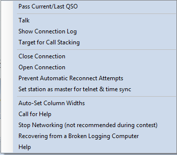
- Pass current/last QSO – If you right-click on a computer to which you wish to pass your current or last QSO (assuming that the station just worked has agreed to QSY), and then click this option, a Talk message will be sent to the Info window of the target computer, telling the other operator who to expect and on what frequency. If that computer’s Pass Frequency is set to zero, then the Message will show the receiving computer’s frequency at that time.
- Talk – A right-click on any computer in the network, followed by a click on this option, will open the Talk sub-window with that computer’s name already entered.Talk messages appear in the Info window of the receiving computer.
- Show connection log – Right-click on a computer and then on this option, and a log of communications events between your computer and the one selected will be displayed as an aid to trouble-shooting.
- Target for call stacking – The intended use of this feature is for large multi-ops that have more than one radio on a given band, to permit the “helper” operator to identify and queue stations for the run operator to work. If the two computers are on the same frequency (+/- a small tolerance), a right-click on the target computer turns on call stacking. Thereafter, any callsign that the “helper” op enters in his Entry window will appear in the call-frame of the target computer’s Entry window. The run operator only needs to hit [Space] to pull the call down into the call-sign textbox, ready to work. There is a checkbox on the Options tab which, if selected, will clear the sending computer’s Entry window if the target computer works the station that has been stacked.
- Close and Open connection – These options are used to open and close connections between the current computer and the one you right-clicked on.
- Prevent automatic reconnect attempts – used when trouble-shooting the network to stop the selected computer from sending reconnect requests every thirty seconds.
- Set station as master for telnet and time sync – Another way to set any given computer on the network as the Master for receiving DX cluster spots and performing time synchronization. Note that time synchronization requires that N1MM Logger+ be run as Administrator on the receiving computer(s).
- Auto-set column widths – used to adjust the format of the Stations display to the minimum required to display the information currently present on-screen
- Call for Help – Sends an audio request for assistance to the computer you clicked on, together with a text message in the receiving computer’s Info window.
- Stop Networking (not recommended during contest) – self-explanatory.
- Help – when Internet access is available, displays the appropriate section in the User Manual.
What, Another Right-Click Menu?
There is a second right-click menu associated with this tab. It is made visible when you right-clink on the column headings row of the tab (“Computer”, “IP Address”, etc.) . It allows you to select which columns on the Stations tab you want to display, in the event that you want to minimize required screen space while still monitoring network activity.
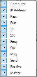
Adjusting the Stations Tab’s Format
If you put your cursor between column headings in that row and move it rightward almost to the next column to the right, you’ll see that it changes to a standard Windows “change width” character (a vertical line with horizontal arrows facing away from it). You can drag that marker right to increase the width of the column to its left, or left to decrease the width of that column.
It is possible using this control to make the heading of a column disappear altogether. If you do that and want to recover, right-click in the body of the tab, and select “Auto-Set Column Widths” to get back to the full set of minimum-width headings.
You can also reorder the columns, by clicking on a column heading itself and dragging it where you want it. Be a little cautious in doing this, though, because there is no command for automatically restoring column order to the original – you’ll have to do that manually or by erasing the NetworkStatus.ini file in SystemFiles directory.
The Resynchronize tab
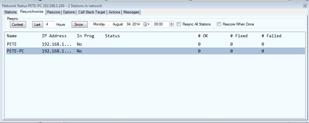
Normally every computer has a copy of every QSO in the log. If all computers stay connected at all times, new QSOs entered on one computer are broadcast to the other computers in the network so that every computer always has a complete copy of the log.
If it is necessary to edit or delete a QSO, the computer that the QSO was initially logged from must be used to perform the change. Other computers do not have permission to change the QSO. Any such change made at the originating computer will be reflected on all computers that are connected to the network at the time the change is made.
If a computer becomes disconnected from the network, you can continue to log contacts on it. When the computer rejoins the network, all QSOs made on that computer will automatically be sent to the other computers, and all new QSOs made on the other computers will be copied to the rejoining computer. This process is called resynchronization (resync for short).
Resynchronization of newly added QSOs is automatic. However, if changes (edits or deletions) are made to previously existing QSOs while a computer is disconnected from the network, those changes will not be applied during the automatic resync process. In other words, the automatic resync when a computer reconnects to the network only updates new QSOs; it does not update QSOs that were already in the log. Because of this, it is a good idea to perform an additional manual resync at the end of the contest in order to ensure that all the logs are identical, and that is the purpose of this tab.
A manual resync operation initiated from this tab requests each other computer in the network to update the requesting station’s copies of all QSOs that were originally logged at the other computer in order to take into account the effects of any changes (edits or deletions) that were made during network outages.
- The “Contest” button will resynchronize from the start of the contest.
- The “Last” button and the textbox next to it are used to resync for a shorter period when you know when the problem occurred.
- The “Since” button works the same way but by resync start date and time rather than duration.
- The “Resync All Stations” checkbox syncs each log with all others simultaneously. Use this after the contest is over to ensure that all logs are identical. This can be a resource-intensive process; in order to avoid disrupting operations at other computers, do not use it during the contest while any computers are still being used to log new contacts.
- The “Rescore When Done” checkbox rescores the contest after the resync is complete on this computer, or all computers if Resync All is selected
The Rescore tab
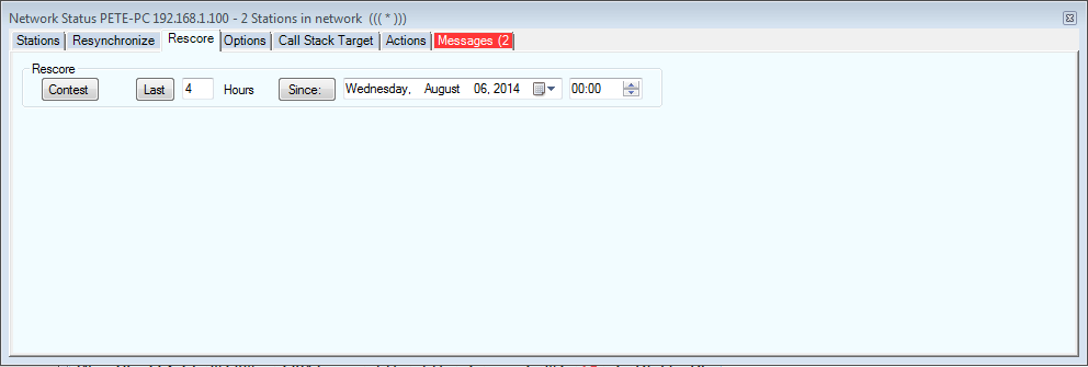
This tab controls rescoring the log on the local computer, recalculating QSO points and multipliers, in order to take into account the effects of any changes (edits or deletions) on the final score. This is recommended practice at the end of a contest, before a Cabrillo file is generated for sending to the contest sponsor. The buttons are the same as those on the left-hand side of the Resynchronize tab, and are used similarly .
The Options tab
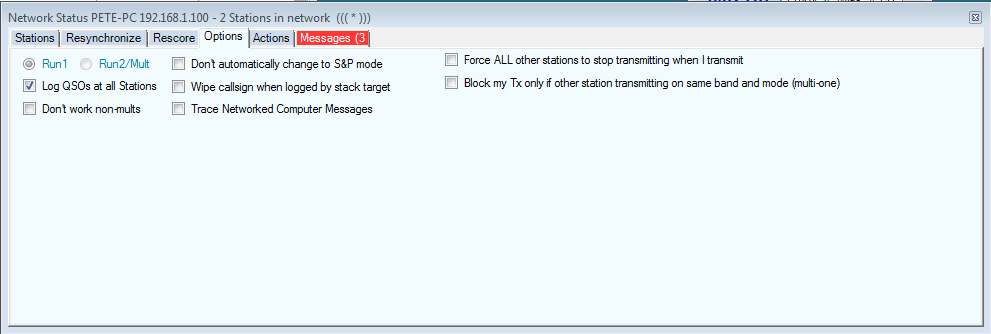
Left to right and top to bottom, following is a description of the radio buttons and checkboxes on this tab.
- Run1/Run2 radio buttons – these buttons are greyed out except in the case of the Multi-2 class, in which case you can click the radio button to designate the current computer as Run 1 or 2.
- Don’t work non-mults – check this box if you are entered in the multi-single class in contests where the current computer must not work non-multipliers. When checked, will block the station from working non-mults. Function key messages will not be sent to a non-mult.
- Don’t automatically change to S&P mode – When checked, prevents the current computer from switching from Run to S&P mode when QSYing by more than the tuning tolerance for its mode. See this page for more details on per-mode tuning tolerance.
- Wipe callsign when logged by stack target – Use in conjunction with call stacking. If you stack a callsign for your partner to work, and he works it, your call-sign textbox will automatically be cleared so you can stack another.
- Trace Networked Computer messages – a trouble-shooting tool that logs messages between computers on the network to a file titled MultiUserMessages.txt
- Force ALL other stations to stop transmitting when I transmit – self-explanatory
- Block my Tx only if other station transmitting on the same band and mode (multi-one) – self-explanatory
The Actions Tab
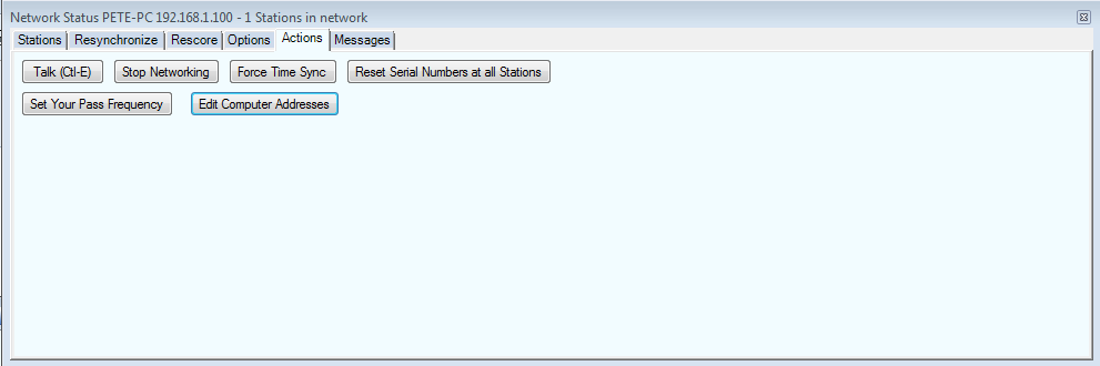
- Talk (Ctl+E) – opens a sub-window, in which you can send or receive talk messages to/from the other station(s) on the network.
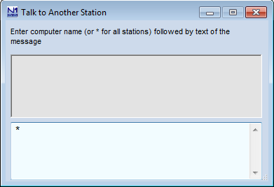
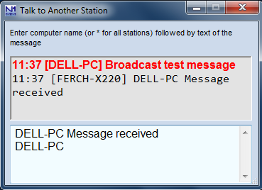
The first of these two illustrations is an empty Talk window. By default, Talk messages are sent to all stations, denoted by the asterisk. If you enter a computer name in place of the asterisk, followed by a space and the text of a message, the message will be sent only to that station. That computer name then becomes the default address for Talk messages from you until replaced. Note: you must enter the computer name exactly as shown in the left-most column of the Stations tab, except that whatever case you enter will be changed to all upper-case to conform with the Microsoft standard.
The upper pane is now where talk messages are received, as in the second illustration. Messages in red have been received, and are also displayed in the bottom pane of the Info window, Ctrl+E can now be used to toggle the Talk window between full size and minimized to the lower left corner of your screen.
The first time you receive a Talk message while the Talk window is open but minimized, you will notice a new icon in the right-hand end of the Windows taskbar, with a message balloon above it. The icon will remain there until the Talk window is closed. This is in addition to the N1MM+ logo you will see over to the left, which is present any time the program is open. Thereafter, each time a new talk message comes in while the Talk window is minimized, a message balloon will appear above the new icon, as illustrated below. The message balloon is displayed for 5 seconds and then disappears.
If you want to send a message only to a particular station, right-clicking on that station’s line on the Stations tab and then selecting “Talk” will relieve you of having to fill in the computer name. Other operation is as above.
- Set Your Pass Frequency – enter the frequency you want other stations on the network to pass stations to. It will appear on all stations’ Stations tab.
- Stop Networking – Self explanatory – strongly discouraged during a contest.
- Force Time Sync – Self-explanatory
- Edit Computer Addresses – N1MM Logger+ networking is automatic within a single subnet, which is usually the case in local area networks. However, if you want to network across a Wide Area Network, or in rare instances where your network involves more than one subnet, auto-configuration will not work. In that case you will need to fill in computer addresses in this table exactly as assigned by the network(s). For WAN networking you must enter the external IP addresses of each LAN and also port numbers for all the computers you wish to connect to, in the format XXX.XXX.XXX.XXX:port number}. Separate port numbers are needed for computers outside the local network, in order to permit operators to set up forwarding through their router firewalls to the right computer. If going subnet-to-subnet, you do not need to enter port numbers and the IP addresses would be the internal IP address. Here’s an example in the WAN case, such as would be needed for a distributed IARU HQ “station”. Note that the Hostnames are the Netbios (computer) names of the computers being networked. In this example illustration, for clarity the computer Netbios names have been reassigned in the illustration to denote the various bands:
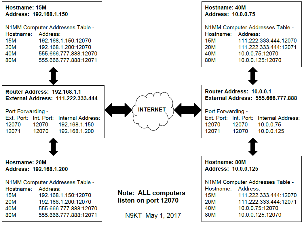
- Please refer to your router help file for instructions on setting up port forwarding. Here is a sample Netgear Port forwarding setup. In this example, the site has two N1MM+ instances running on 192.168.1.7 and 192.168.1.8. The router will receive TCP connections coming in on port 12071 and 12070, but both connections will be sent to 12070 on their respective computers. 13064 is a spectrum UDP port being forwarded to 192.168.1.7
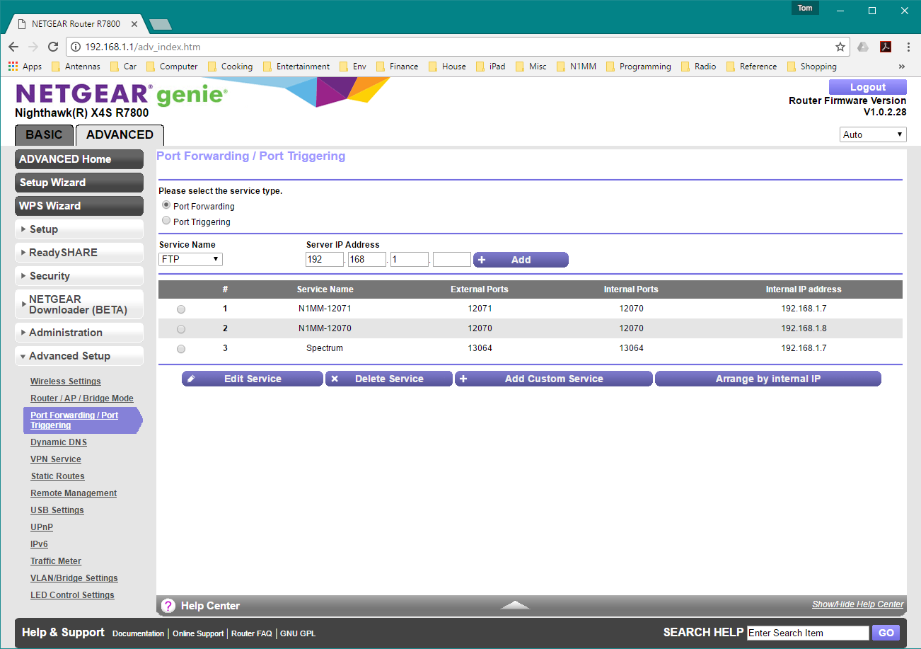
- Reset Serial Numbers at All Stations – only for use when you have screwed up. Sets the serial numbers on all computers to the highest value in any of the logs, plus 1, so you can start a new serial number sequence without duplicate numbers. This does not change the serial numbers of QSOs that are already logged.
The Messages Tab
Displays networking messages
Troubleshooting
- Check first:
- All computers have different Netbios (computer) names and they are all 15 characters or less
- All computers are running the same version of N1MM+. Please use the latest version
- All computers have the same time with 2 seconds or you are running all the non-master computers in admin mode so they can set the time when the master requests it.
- All computers have the same copy of Master.SCP and wl_cty.dat
- Computers don’t connect at all, or connect in one direction only
- If computers are not on the same subnet, they will not automatically connect. Enter their Netbios names and ip addresses in the computer addresses table – see Actions Tab to access
- Start without a computer address table – make sure you do not have any entries in it. If you need entries, make sure they are correct. – see Actions Tab to access
- Make sure each computer is allowed to connect to other computers by Windows firewall or any other firewall. It may be quicker to turn off the firewall and test. If that solves the problem (like one-way communication), then figure out how to put N1MM+ into the firewall exception list and restart the firewall. We do not recommend running your computer without a firewall
- Remote computers don’t connect
- N1MM+ receives data on port 12070. Routers must translate the port being SENT from remote computers to the particular computer on the network. If you SEND on port 12071 to computer Bob, the router must route 12071 as 12070 to Bob. You will need to route as many ports in your router as there are computers running N1MM+ at that location.
Recovering from a Broken Logging Computer
What do you do if one of your computers no longer works?
DO NOT ADD ANOTHER COMPUTER WITH THE SAME NAME!
If you do not replace it on the network
- Each computer will have a copy of the QSOs logged by the broken computer. If they all agree on the number of QSOs, then you should be fine. If not, you will need to compare the lists from each one and determine which QSOs are missing.
If you replace it on the network
- Locate a running network computer whose log includes the QSOs from the broken logging computer. SHUT THE PROGRAM DOWN on this computer.
- Copy that computer’s <log>.S3DB. <log>.s3db-wal and <log>.s3db-shm database files (The last two are temporary files that usually do not exist) to a network drive, diskette or flash drive.
- Copy the <log>.S3DB* database files from the temporary medium to the replacement computer’s \database directory
- Configure the replacement computer and N1MM Logger and begin logging. Any new QSOs will be identified by the replacement computer’s name, which MUST NOT be the same as the broken machine’s name.
- Restart the source computer and resume logging
NOTE:
Each computer is the “book of record” for the QSOs logged on that computer, even though all QSOs are normally logged on every computer for redundancy. Resync simply compares what your computer’s log shows for QSOs by a particular computer (as identified by its network name) to what that computer has in its log. If there is a difference, the computer that logged the QSO sends the updated QSOs to the requesting computer. If a QSO is deleted or removed from the log in the computer that “owns” the QSO (as identified by the computer’s name), the Resync operation will delete that QSO from the logs in the other computers.
Therefore, if the problem was with the database on the “broken” computer, DO NOT create a new database (or a new contest within the existing database) on the problem computer in order to resolve the problem. That will cause all the QSOs that were formerly logged on that computer to disappear from all of the logs. Likewise, DO NOT swap in a new computer with the same name and a new empty log, as that will have the same effect. To avoid this, make sure the name of the new computer is different from the name of the broken computer (the computer name can be changed in Windows if necessary to avoid duplication).
The best way to avoid all this is to keep a spare computer (with its own unique network name) up and running N1MM+ on the network. You can then just swap it in for the broken one. The QSOs from the broken computer will still be in the logs in all the other computers.
-16- The Spectrum Display Window
Spectrum Display Window – If your red dots don’t line up with signals, adjust the noise floor. Then use Shift+up/down to jump from signal to signal!
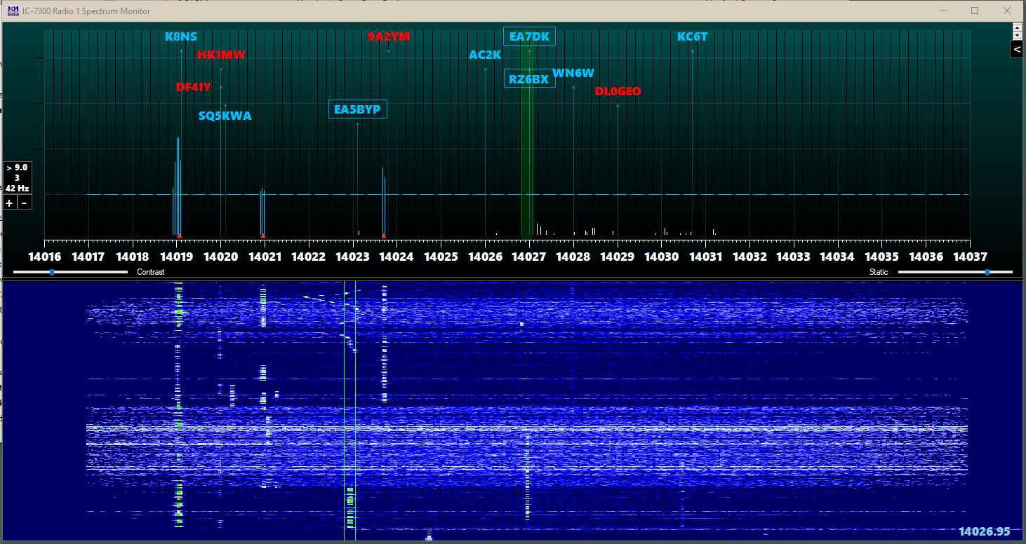
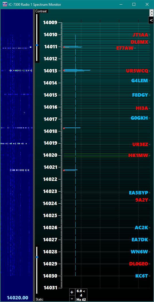
The Spectrum Display Window is a window that takes advantage of CAT spectrum output from certain radios. It also supports displaying spectrum data from other programs via its UDP interface. What is unique about the N1MM+ Spectrum Window is its ability to identify signals and allow the user to jump to those via keystroke as well as compare them to local and RBN spots to identify unspotted and already worked signals.
Supported Radios & Interfaces
SDR Radios via SDR Vendor Provided ExtIO*.dll (This is an experimental feature)
- Download the correct ExtIO dll from the vendor website and place in the N1MM+ *Program Install* directory. This usually C:\Program Files (x86)\N1MM Logger+. (Some radios, like the IC-7610 require addtional files. Read the radio’s documentation for using HDSDR with the radio and emulate the install instructions, but put in the N1MM Logger+ directory.)
- Start N1MM+ and open a Spectrum Window. Right-click and set the source to “I/Q via ExtIO.dll”
- Select the correct dll in the “<” IQ tab.
- Tested radios include: SDRPlay RSP1, RSP2, Airspy HF+, Icom IC-7610.
- A link to the Airspy HF+ extio dll can be found in Airspy HF+ page in the “Supported Software” section.
- Be sure to install the driver for the SDR if required. SDRPlay would need you to install SDRUno to install the USB driver.
- You can only run one program at a time using the output of an SDR. Don’t try to run SDRUno and N1MM+ spectrum at the same time.
- Other radios may need the “Reverse I/Q” checkbox checked if the spectrum moves in the wrong direction. Notify the team and we will include the Radio to select I/Q properly. We will need to know the ExtIO*.dll name for your radio.
- I don’t plan to support any other radios at this point. Why? Two reasons. SDRs are very idiosyncratic in how they work. Each seems to have its own set of issues. I don’t have all these radios to debug (and I don’t want to have them). The second reason is that owners usually just say something like “I tried the spectrum window with my Toothgnasher SuperSDR and it doesn’t work. What gives?” There is not a lot to go on to debug that. You might want to report what settings you used, and the actual symptoms.
IC7610 using native FTDI interface (This is an experimental feature)
- Download the correct Icom HDSDR installer. This will install the USB driver. Install it with the radio disconnected.
- Install a USB cable from the second USB port on the rear of the IC7610 to your computer.. tart N1MM+ and open a Spectrum Window.
- Right-click and set the source to “IC7610 I/Q via FTDI.dll”
- Note that the IQ tab dll combox will hide any IC7610 Extio dlls. They are no longer needed. This connection allows choosing of main/sub rx by selecting the Associated radio. The ExtIO.dll version did not.
Icom IC-7300, IC-7850/51, IC-7610
- Must use the USB cable virtual COM port for radio control. Unplug the CI-V cable.
- Set Right-Click Radio source to Radio 1 or Radio 2 as appropriate
- Must have the radio menu CI-V USB Port set to Unlink from [Remote}
- Must have the radio and program baud rate set to 115200 baud.
- After the program and the radio is set to 115200 baud, exit the program and restart.
Flex 6300/6400/6400M/6500/6600/6600M/6700 Radios Supported via CAT and UDP – requires SmartSDR V2.0 or later software
- If a supported Flex radio is detected, N1MM+ will send commands to the radio to start and stop the spectrum. It will send your local IP address and port 13064 to the radio. Note that the program can get confused if there is more than one local IP address in the computer, e.g. a NIC connected directly to the Flex separately from the NIC or WiFi adapter connected to the LAN. Therefore, do not connect your Flex directly to the computer via Ethernet. Connect the Flex to the radio via your router so that the network adapter connected to the LAN is the only one active in the computer.
- The Spectrum Window should automatically find the Flex spectrum feed if it is already sending it. Otherwise, start the Flex and do the following
- Start a new Spectrum window and select External (“For all other radios, source named…”) as the source. The Flex should already be transmitting its identifying information, so when you go to choose the source, pick the source you want from the drop-down list
- Resolution in the N1MM+ spectrum display will be dependent on the zoom level of the Flex panadapter. Bear in mind that the precision of the signal marking is dependent on the zoom level & consequent bin/pixel size. Something between 20 and 50 Hz per pixel would be a good place to start
Elecraft K3/K3S/KX3 plus software/hardware:
- Win4K3Suite ( https://va2fsq.com/ ) software plus hardware as described below:
- K3S, or K3 with KXV3, plus LP-PAN or SoftRock II Lite, plus stereo sound card – connect LP-PAN or SoftRock to IF Out, set right-click spectrum source to “For all other radios, source named > Win4K3Suite”. See Win4K3Suite documentation for Win4K3Suite software setup
- K3S, or K3 with KXV3, plus SDRPlay (RSP1 or RSP2) – connect SDRPlay to IF out, see Win4K3Suite documentation
- KX3 plus stereo sound card – see Win4K3Suite documentation
- KX2 plus SDRPlay (RSP1 or RSP2) plus an external transmit/receive switch – see Win4K3Suite documentation
- Waterfall bandmap ( https://groups.io/g/waterfallbandmap ) software plus hardware as described below:
- K3S, or K3 with KXV3, plus LP-PAN or SoftRock, plus stereo sound card:
- Connect LP-PAN or SoftRock to IF Out. Put WB in Sound Card mode, Offset with LP-PAN is approx. -6000 (varies with mode, roofing filter offset, SHIFT control settings). If traces move the wrong direction in the waterfall when tuning, check (or uncheck) Swap I&Q. Swap I&Q checked/unchecked setting for 6m is opposite to the setting for HF. Set right-click spectrum source to “For all other radios, source named > Waterfall Bandmap”
- K3S, or K3 with KXV3, plus ExtIO-capable SDR (including SDRPlay):
- Put WB in ExtIO mode (ExtIO dll must be in the WB program directory)
- RF-based: Connect SDR to a splitter in a jumper between RX Ant Out and RX Ant In – RX Ant must be selected in the K3. Offset zero, SDR at IF check box unchecked.
- IF-based: Connect SDR directly to IF Out. Check the SDR at IF check box, set IF to 8215, Offset to zero as a starting point, but offset varies with mode, roofing filter offset, SHIFT control settings. May need to check Swap I&Q if traces move in the wrong direction when tuning – 6m and HF will be opposite settings for this, and offset settings may also differ between 6m and HF. Set right-click spectrum source to “For all other radios, source named > Waterfall Bandmap”
- Put WB in ExtIO mode (ExtIO dll must be in the WB program directory)
- KX3 plus stereo sound card:
- Connect KX3’s I/Q output to the sound card. Put WB in Sound Card mode. Offset zero. If traces move the wrong direction in the waterfall when tuning, check (or uncheck) Swap I&Q.
- K3S, or K3 with KXV3, plus LP-PAN or SoftRock, plus stereo sound card:
Yaesu FTDX5000, FTDX3000, FTDX1200, FTDX9000, FT991 plus Win4YaesuSuite ( http://yaesu.va2fsq.com/ ) software plus hardware as described below:
- LP-PAN plus stereo sound card (FTDX5000 or FTDX3000 only) – connect LP-PAN to IF Out, see Win4YaesuSuite documentation for software setup
- SDRPlay (RSP1 or RSP2) – connect SDRPlay to RX out or IF out (depends on radio model), see Win4YaesuSuite documentation for hardware and software setup
Waterfall Bandmap Software
https://groups.io/g/waterfallbandmap
- SDRPlay, FunCubeProPlus, HackRF, LP-PAN, SDR-IQ, RTLSDR, SoftRock, etc. – SDRs and panadapters that produce I/Q output either via ExtIO.DLL or via a sound card can be used together with almost any transceiver using Waterfall Bandmap software
- The SDR may be connected to an antenna, to an RX Ant output on some transceivers, or to an IF output on transceivers that have an IF output. Note that if the SDR is connected directly to an antenna, an external TX/RX switch may be required to protect the SDR against RF from the transmitter.
- Start Waterfall Bandmap after starting N1MM+ but before starting the N1MM+ spectrum display window. Configure Waterfall Bandmap according to the Waterfall Bandmap documentation.
- The Spectrum Window should automatically find the spectrum feed if Waterfall Bandmap is already sending it. Otherwise, start Waterfall Bandmap and do the following
- Start a new Spectrum window and select External (“for all other radios, source named…”) as the source. The Waterfall Bandmap should already be transmitting its identifying information, so when you go to choose the source, pick Waterfall Bandmap from the drop-down list
- If you find “smearing” of the blue spectrum lines while tuning, use the right-click option “Reduce spectrum smearing while tuning” to clear spectrum data each time the frequency is changed. This is needed because the source is getting the radio frequency information after the spectrum window gets it.
- RF or IF > SDR/panadapter > Waterfall Bandmap > N1MM+ Spectrum Window
- SDRPlay
- In Waterfall bandmap, select configure and set the SDRPlay’s IF Mode to Low IF and the IF Bandwidth to 200 kHz. Adjust the LNA & gain controls to limit the amount of noise generated when strong signals are present. The noise will appear as traces in the waterfall, but there are no signals there. The traces will occur coincident with the strong signal transmitting and will occur at various places in the spectrum. The SDRPlay has very high gain to work with short, inefficient antennas, you don’t need much gain with a beam or full size dipole.
- Use the zoom control in Waterfall Bandmap to set the zoom level as shown in the box on the left hand side of the spectrum window to about 40 Hz/pixel or less for CW & RTTY and to about 100 Hz/pixel for SSB. Higher numbers will result in poor signal detection accuracy.
KE9NS PowerSDR
Supports the Spectrum Window as of version 2.8.0.43 (6/29/17)
http://ke9ns.com/flexpage.html
- Start PowerSDR before starting N1MM+
- The Spectrum Window should automatically find the spectrum feed if it is already sending it. Otherwise, start PowerSDR and do the following
- Start a new Spectrum window and select External (“for all other radios, source named”) as the source. The radio should already be transmitting its identifying information, so when you go to choose the source, pick the source you want from the drop-down list
CW Skimmer version 2.0
http://www.dxatlas.com/cwskimmer/
- In CW Skimmer’s Settings window, select the Network tab and check the “Send Spectrum via UDP” box to send spectrum data to the N1MM+ spectrum window.
- In the Spectrum window, select External (“For all other radios, source named”) as the source and pick CW Skimmer from the drop-down list.
Airspy HF+
No other Airspy models are supported
- Download SDR# software to downloads from https://airspy.com/download/
- Create a new directory SDR# on your C drive (i.e. C:\SDR#) or in your N1MM+ *program* install directory (typically, C:\Program Files (x86)\N1MM Logger+\SDR#).
- Copy all the files from the downloaded SDR# to the new directory. If you want to start the server manually, you can put it wherever you want.
- Important: Change the device_type= in spyserver.config to AirspyHF+
- Change fft_fps= to 6. This improves cpu consumption
- Start N1MM+ and open a spectrum window
- Right-click and set the Source for the spectrum window to Airspy HF+
- If there are bugs in setup, closing the program and restarting at this point may clear them. I need to fix them, but you probably want to get on with using it at this point.
- There is code included for local Airspy servers to suppress the spectrum & waterfall displays for 200 msec after the associated radio stops transmitting. It will also suppress the display if a very strong signal is present on the transmit frequency.
- To add a second Airspy HF+ you will need to:
- Specify the airspy serial number that you want to serve in spyserver.config. That should show up in the window that runs when you start it.You may have to connect them one at a time to figure this out.
- Change the bind port from 5555 to 5556 (or whatever)and bind to that port in the 2nd spectrum window “<” pane Connect tab.
- You will need to start a second copy of spyserver manually with the different ini file.
Other vendors TBD
- Start the source before starting the N1MM+ spectrum window
- The Spectrum Window should automatically find the spectrum feed if it is already sending it. Otherwise, do the following
- Start a new Spectrum window and select External (“For all other radios, source named”) as the source. The source should already be transmitting its identifying information, so when you go to choose the source, pick the source you want from the drop-down list
Layout
Spectrum Pane
- The spectrum is displayed in the top or right-hand pane, depending on the orientation you choose. Since the option defaults to “Auto” the orientation will change depending on the dimensions of the spectrum window
Waterfall Pane
- The Waterfall pane, when the show waterfall option is selected will appear at the bottom or left of the spectrum pane. Note that in portrait (or bar-chart) mode, the waterfall moves from right to left so that one can see the start and stop of sending and potentially read cw for sources that refresh at a rapid enough rate.
Setup, Connect I/Q Panes
Click the “<” to access
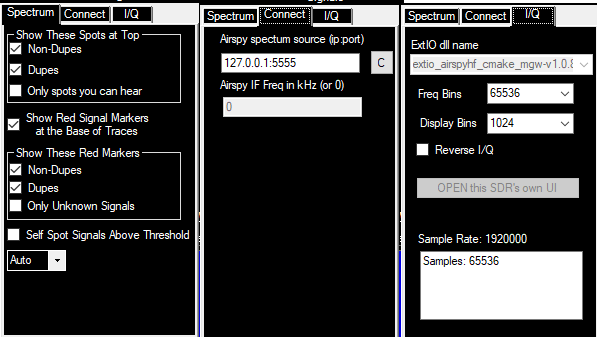
- These panes are accessed by clicking on the “<" or ">” button at the top right (just below the font sizer arrows) to open or close it
- Setup Pane
- At the top is the legend for colors in the spectrum display
- The display can show spots superimposed on the signals. These spots can be from Telnet (assisted or multi-op), or locally generated by logging QSOs or entering a call and tuning away from that signal (all categories). “The Show These Spots at Top” lets you control which, if any spots are shown. You can even restrict the spots to only those that have signals recognized by the software that are within the tuning tolerance of the spot. If the associated radio is tuned to the spot, the callsign with have a box drawn around it
- The “Show Red Signal Markers at the Base of Traces” will display a marker everywhere the software determines there is a signal. When you press Shift+Up/Down, the associated radio will jump to the red markers
- Show these Red Markers allows you to restrict which signals are marked in the window. Typically you will want to show markers for Non-Dupes (signals you can work) but not show markers for Dupes (which includes zero point QSOs).
- If you want to watch for new signals on a band before the Reverse Beacon Network spots them, check show “Only Unknown Signals”, but jump on them fast, because somebody’s skimmer will be spotting it within seconds!
- Static sensitivity removes samples from the display if certain criteria are met that make a sample look like a static crash. If you are getting lots of false signals due to static crashes, raise the Static Sensitivity until most are removed.
- The control shown as “Auto” above controls the orientation of the spectrum display. If you leave it on Auto, it will pick the right orientation based on the shape of the window
- Signals detected by the Spectrum Display that are above the noise threshold, but without a previously identified callsign will put spots of the form @frequency in the bandmap and available windows for tracking unknown signals, provided the option to do so has been selected in the setup pane.
- Connect Pane
- This pane allows specification of an Airspy HF+ SpyServer source other than 127.0.0.1:5555. It is restricted to LAN addresses when logging in contests. If the DX Log is open any address may be specified.
- If using the Airspy HF+ at IF, enter the IF frequency on the Connections tab of the setup pane. You may have to adjust it by mode.
- I/Q Pane
- On this pane enter ExtIO.dll names for accessing SDRs.
- For ExtIO supported SDRs and for IC7610 supported via FTDI I/F, you may enter the number of frequency bins for fast fourier transform. The higher the number of bins, the higher resolution possible. It will also use more cpu time. The program keeps the zoom level constant (if possible) when this is change. You will need to zoom (+/-) to see different zoom levels.
- Display bins is also settable for these SDRs. Using a higher number than the number of pixels on your spectrum window will just use more cpu time.
- Reverse I/Q is off automatically and is not needed for supported radios. Fro non-supported radios, check it if the display does not match the heard signals.
- The open button allows the user to display the UI for the SDR. Always close the display with this button not the “X” button in the SDR UI.
- Sample rate is the SDR’s reported sample rate.
- Setup Pane
General Setup
- Keep the noise level low by setting the ref level (whatever control sets the “grass” level in the source’s spectrum display) in the radio menu low
- For supported Icom and Flex radios, the spectrum scope will be turned on startup and turned off on exit
- The window can be opened from the Entry Window “Windows” menu.
Controls
- With focus set on the Entry Window, Shift+up will move the frequency to the next signal up in frequency. Shift+down will move the frequency to the next signal down in frequency. This is the reverse of bandmap functions which are oriented towards the display of frequencies rather than their value.
- If you use the spectrum display in the vertical (bar chart) orientation, there is a right-click menu option to change the direction of movement to match the direction of bandmap functions.
- Show signals will show all the signals the window has identified on the frequency axis using your multiplier background color. These signals are also counted in the box that shows the noise floor and pixel width in Hz.
- Shift+up/down will *skip* signals that are within tuning tolerance of dupes and non-workables, depending on the options you have chosen in the setup pane.
- Shift+up/down will stop at the low and high frequencies in the spectrum. If you are using center mode, the spectrum will re-center on the low or high edge frequencies as appropriate
- Use the up/down keys to fine-tune signals. If the tone is too high, press the down key. Use the up key for signals too low in tone (depends on the sideband in use, i.e. CW-R will be opposite to CW).
- Sig (db) is level of signal as shown on the display, relative to ref and includes the preamp level
- Snap to sig – when checked jumps to the nearest signal when you click on the chart. (within 2 kHz)
- The noise floor threshold is adjustable with the mouse wheel.
- Signal count is the number of “signals” found above the noise floor reference. Roughly equivalent to how many times your cursor will stop traversing the screen. The count includes non-workable spots.
- To mark signals that you don’t want to work, use the Mark button (Alt+M to mark, Alt+D to remove)
- The Static Sensitivity slider should be adjusted until large static crashes light up the “Static Sensitivity” label
- Left single click on the spot label will QSY your Rx & Tx to the frequency of that spot – including split. If you have the noise floor, source level and static sensitivity set properly, you will find that clicking on the spectrum will usually tune the signal more accurately than a cw spot. Note that you must have “snap to signal” turned on for this effect.
- +/- zooms the spectrum in/out. Not all SDR sources support this function. If not supported, the +/- boxes will be hidden. These zoom boxes appear under the threshold/sigs/Hz box.
- Alt+Q still returns to your CQ frequency. Alt+F8 still returns to your last frequency
Mouse (see also the Strange and Mysterious Mouse Wheel, below)
- Left click will set radio receive frequency and snap to closest signal if check box is checked
- Ctl+left click will set split frequency to that frequency. Snap to signal is ignored
The Strange and Mysterious Mouse Wheel
The mouse wheel is used for a number of functions in the Spectrum Window. Lets look at them by pane:
- Spectrum Pane
- When the mouse is over the main portion of the spectrum, the mouse wheel controls the noise floor. You will see the blue dashed line move up and down
- With Icom radios, holding down the Ctl key while moving the mouse wheel in the main portion of the spectrum window will control the REF level of the radio’s spectrum
- With the Airspy HF+, holding down the Ctl key while moving the mouse wheel in the main portion of the spectrum window will control level of the spectrum. Scrolling all the way down will set the level to Automatic
- With the Airspy HF+, moving the mousewheel when the cursor is over the frequency scale and the Airspy scrolling mode is Fixed, will shift the spectrum frequency
- When the mouse is over the contrast slider, it will control the color of the Waterfall in the pane below. Yeah, I know it belongs in the Waterfall pane, but it flickered badly. You’ll like it better where it is
- When the mouse is over the static sensitivity slider, it will control how much static is detected and discarded. Static does not show in the waterfall
- When the mouse is over the left of spectrum in a landscape/column mode spectrum or over the top of the spectrum in a portrait/bar chart mode spectrum, it will control the dB range displayed. Use the “<” & “>” buttons to see the dB scale
- Waterfall Pane
- When double vertical bars are displayed, and the mouse is in the Waterfall pane, moving the mouse wheel will tune the radio. Adjust the CW/SSB/Digi tuning values in Configurer/Other tab to your liking and the speed of your radio’s CAT. The frequency as you tune will show in the lower part of the Waterfall. Note that this is the radio reporting back the frequency, so depending on the radio there may be a little lag or a whole lot. If you press Ctl or Shift while turning the mouse wheel, the radio will make larger frequency jumps, just like it does in the Entry Window. The main purpose of this tuning is to allow you to fine tune a signal after clicking on its trace in the Waterfall
- Other
- The mouse wheel will change the dB scale range when the mouse is positioned above (column mode) or to the right of (bar mode) the noise floor/signals/resolution box.
The Right-Click Menu
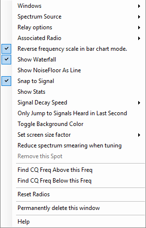
- Right-click opens a context menu
- Windows – lets you choose between spectrum windows that have been configured
- Open a new window – to create a new spectrum window
- Spectrum Source – Sources heard by the software will be shown as choices. Until a source name shows up in that drop-down menu, it will not display, or will be greyed out, as it is not being received
- Radio 1 (Icom 7300/7851/7851 only) – if one of the specified radios is configured as Radio 1
- Radio 2 (Icom 7300/7851/7851 only) – if one of the specified radios is configured as Radio 2
- For all other radios, source named – opens a submenu with a list of any other sources that have been named. External software sources supply their own names. Spectrum data forwarded by another N1MM Logger+ user is named according to that user’s choice in the Relay Options
- Relay Options – allows you to provide the spectrum displayed in this window to another N1MM Logger+ user.
- Do not relay this spectrum (default)
- Broadcast on IP ports(s)… – Enter list of IP addresses: data is sent to the user specified IP & port. The only port that N1MM+ will listen on is 13064, so only use another port to provide port forwarding with a router at another site
- Name of this source – the name which the other N1MM Logger+ user will use to access this spectrum source
- Associated Radio – assign which radio will change frequency when you jump to signals from this window (Radio 1 or Radio 2)
- Reverse frequency scale in bar chart mode – if you check this option, the low frequency of the spectrum will be at the top, matching the way the band map is oriented
- Show Waterfall – controls whether the waterfall is displayed. When the waterfall is displayed the current radio frequency will appear in the waterfall pane. When it is not displayed, the current frequency appears in the spectrum pane
- Show Noise Floor as Line – This is effective only in column (landscape) chart mode. Instead of columns, the instantaneous signal values will be shown as a line and the (decaying) average values that exceed the noise floor will show as a filled line series
- Snap to Signal – When on, clicking on the spectrum will jump to the nearest signal center rather than to the precise point which you click. It will look +/- 2 kHz for a signal
- Show Stats – shows information that the window has collection about the currently displayed spectrum. It will remain for 25 seconds, or click on the X to hide it
- Signal Decay Speed – Controls how fast the blue signal indicator lines decay. For SSB, if you set the signal decay speed to fast, it will find signals more accurately, but skip signals not transmitting at that instant. Use fast for SSB and crowded conditions, slow for quiet bands.
- Use Alternate Signal Detector – If there is an alternate signal detection algorithm being tested, you can select it here.
- Round SSB Sigs to nearest 0.5 kHz – experimental option to help with regular dxing. This is not expected to be useful in a contest. Non-sticky to prevent its inadvertent use during a contest
- Only Jump to Signals Heard in the Last Second – Shift+up/down will ignore any signals that are not currently transmitting (experimental)
- Toggle Background Color – to toggle to higher contrast backgrounds – both white & black. Black background is the most readable.
- Set screen size factor – Submenus let you choose between 1x, 2x or 3x the number of pixels sent by the source. The control will not have to interpolate points if you choose one of these. The size of the spectrum window does NOT affect the finding of signals. That is always done with the incoming source data, not the data as displayed
- Reduce spectrum smearing when tuning – some sources that follow the radio’s frequency receive updated vfo frequency data after they have sent updated spectrum data to the program. This will cause the data in the spectrum window to “smear”. Selecting this option will clear old spectrum data whenever the frequency limits of the spectrum source changes
- Remove this spot – does what it says, but is only enabled when you hover over a spot in the spectrum panel of the window.
- Find CQ Freq above this Freq – Find the 2.5 or 0.4 kHz slot in the current spectrum that has the least energy displayed in that slot. This is affected by Signal Decay Speed
- Find CQ Freq below this Freq – Same as above, but in the opposite direction
- Reset Radios – Sends the commands to reinitialize the radios connected to the program (similar to the same option in the Bandmap window). This will often restart the spectrum display on a supported radio.
- Permanently Delete this window – close this window and delete its configuration. It will no longer show in the spectrum window list. For use when you have created multiple spectrum windows
- Help – link to this documentation
- Windows – lets you choose between spectrum windows that have been configured
Colors
- White is the instantaneous signal level as shown in white on the radio (black on light color skins)
- Blue is a “decaying” representation of the signal *similar* to that on the radio
- The green line is the current Rx frequency
- The horizontal blue line is a measure of the noise floor above which signals are found
- The vertical red line, if shown, is the tx frequency when split
Operation
* Adjust the REF level on your radio (or equivalent in your source) and the mouse-wheel noise floor to the point where the number of signals counted drops suddenly from a high number to a reasonable one. The noise floor is adjustable in 0.2 dB steps from 0-1 dB and in 1 dB steps thereafter. Check that you don’t have the noise floor too high by tuning for a weak signal
- Use the mouse wheel in the chart area to adjust the noise floor. You will see the number of sigs change as you scroll the blue line. If a blue or white signal is above the floor, Shift-up/down will jump to that signal. The noise floor value and # of signals detected are shown in the box near the dB scale.
- Also shown in the little noise floor/signal box is the number of Hz represented by one pixel of incoming data. Note that to see all the incoming pixels, you need to make the graph area of the spectrum window greater than the number of pixels. The number of Hz per pixel affects how many signals can be found. If you have a source generating pixels greater than 100 Hz apart you may lose the ability of the program to find some signals as they are not represented in the source data stream. The size of the spectrum window does NOT affect the finding of signals. That is always done with the incoming source data, not the data as displayed
- If you are short on screen space, Ctl-up/down does not need the old bandmap to be open to work. You can use this one instead
- Turn off “snap to spot” if you find it is interfering with you clicking on signals. You don’t need it if you are zoomed way in as you would often be in center mode
- For DX split operation, use Ctl+click to set the Tx frequency to the point where you think the dx op will answer the next caller. That might be the frequency of the last station that worked him or it might be higher or lower
- Pro Tip: Try setting your up/down tuning increments in Config/Config Ports…/Other to match your preferred zoom level for your spectrum as seen in the left-hand box in the spectrum display. For example, if you like CW resolution at 42 Hz/pixel choose .021 as your up/down increment. For SSB and 105 Hz/pixel, you might choose .0525 as your increment. By choosing multiples, you will minimize jitter in the waterfall display that results from imprecise changes in tuning. Doing this only helps when using the up/down keys to tune or the mouse wheel equivalent.
Relaying and Port Forwarding
The Spectrum Display window can forward the data it receives to another spectrum display window. The other spectrum window can be running in the original instance of N1MM+ or in N1MM+ running on any computer that is reachable via UDP packets. The forwarding computer only sends its spectrum display data: band, frequency, signal strength, display name, scaling factor. The destination instance of N1MM+ is responsible for display settings, the noise floor, and capturing packet spots.
Step 1. Preparing the source instance of N1MM+ to forward its Spectrum Display window
- Using your mouse, right-click in the Spectrum Display window to be forwarded
- From the right-click menu, select >Relay options >Name of this source
- Enter a unique name for this Spectrum Display window. For example, “20M Radio”
Step 2. Preparing and launching the destination Spectrum Display window
Choose one (or more!) of the following options
- Option1. Local Forwarding to a second Spectrum Display in the same instance of N1MM+ (you have only one computer)
- Using your mouse, right-click in the Spectrum Display window to be forwarded (the source window)
- From the right-click menu, select >Relay options >Broadcast on IP/port(s)
- Enter an IP address of 127.0.0.1
- To open the second spectrum display, right-click in the source spectrum display
- From the right-click menu, select >Windows >Open a new window
- In that new window, right-click and select >Spectrum Source >Source named
- Choose the source name that you assigned in the first step of this process. In our example “20M Radio”
- Option 2. Forward a spectrum to another computer on the same LAN (you have more than one computer)
- Using your mouse, right-click in the Spectrum Display window to be forwarded (the source window)
- From the right-click menu, select >Relay options >Broadcast on IP/port(s)
- Enter the IP address of the destination computer. For example 192.168.1.123. You can run IPCONFIG in a cmd window to determine the destination computer’s IP address
- If N1MM+ is already running on the destination computer, close and re-launch N1MM+
- To open a spectrum display window on the destination computer, from the drop-down N1MM+ menu on the destination computer select >Window >Spectrum Display
- In the destination computer’s spectrum display, right-click and select >Spectrum Source >Source named
- Choose the source name that you assigned in the first step of this process. In our example “20M Radio”
- Option 3. Forwarding to remote instance of N1MM+ (you have more than one site)
- Using your mouse, right-click in the Spectrum Display window to be forwarded (the source window)
- From the right-click menu, select >Relay options >Broadcast on IP/port(s)
- Enter the IP address of the remote destination computer. For example 71.233.1.123. From a browser on the remote destination computer, entering “my ip address” will tell you your external IP address
- Set up port forwarding on the router of the remote computer LAN to route incoming port 13064 to 13064 on the destination computer
- If N1MM+ is already running on the remote destination computer, close and re-launch N1MM+
- To open a spectrum display window on the remote destination computer, from the N1MM+ drop-down menu on the destination computer select >Window >Spectrum Display
- In the remote destination computer’s spectrum display, right-click and select >Spectrum Source >Source named
- Choose the source name that you assigned in the first step of this process. In our example “20M Radio”
- Option 4. Forwarding to 2nd remote instance of N1MM+ (you have more than one computer at a remote site)
- Using your mouse, right-click in the Spectrum Display window to be forwarded (the source window)
- From the right-click menu, select >Relay options >Broadcast on IP/port(s)
- Enter the IP address of the second destination computer and specify a different port. For example 71.233.1.321:13900. (cannot be any port currently in use)
- Set up port forwarding on the router of the remote computer LAN to route that new incoming port to port 13064 on the second destination computer
- If N1MM+ is already running on the second destination computer, close and re-launch N1MM+
- To open a spectrum display window on the second destination computer, from the N1MM+ drop-down menu on the destination computer select >Window >Spectrum Display
- In the second destination computer’s spectrum display, right-click and select >Spectrum Source >Source named
- Choose the source name that you assigned in the first step of this process. In our example “20M Radio”
Note that Broadcast on IP/Port can be a comma separated list of IP addresses. For example: 192.168.1.1,79.235.146.132:13064, 29.235.146.132:13900 (separate with a comma, but no spaces)
Netgear Routing Example
In the example below, external port 13064 is being routed to 192.168.1.7 on the LAN. (Line 3 “Spectrum”). This menu is accessed from Netgear’s Advanced/Advanced Setup/Port Forwarding & Port Triggering selection
Notes
- With most SDRs, if you feed a narrower bandwidth slice to the spectrum display, less noise will be sent as well. Try to use wide bandwidths only on quiet bands where you want to scan the whole band for new signals
- Gaps will appear at the beginning and end of the center mode spectrum display if you are not currently tuned to a whole kHz frequency. This is normal
- If your radio is turned off or not configured properly, you may need to close the spectrum display or perhaps close the program and reopen to get the display to work
- We are focusing on CW and RTTY operation. You can play with other modes, but bear in mind little work has been put into making the window play nice with them
- In SO2V only, the second VFO will be shown with a line in your skin’s highlight color
- Use Fast signal decay for SSB signal detection. Slow signal decay can be used with CW & RTTY to keep signals on the screen longer.
- If you detest the tool tips, you can turn them off at the bottom of Config/Manage Skins, Colors and Fonts
SDR Block Diagram
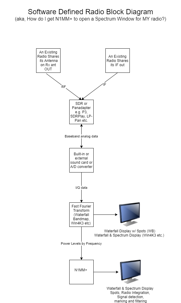
This picture represents non-I/Q support.
For I/Q supported radios (SDRPlay, Airspy HF+ via ExtIO, IC7610 via FTDI), the FFT occurs within N1MM+.
WSJT-X Decode List Window
Introduced on January 2nd, 2019, the WSJT-X Decode List provides a bi-directional interface between WSJT-X’s Band Activity Panel and N1MM+’s contest log.
Key Features
- QSO initiation, auto-sequencing, and logging from within the WSJT-X program
- Contact logging in both the WSJT-X ADIF log and the N1MM+ contest database
- Callsign prioritization (normal, mult, double mult) based on contest contacts in the N1MM+ log
- Dupe callsign warnings based on contest rules (bands, modes) and existing contacts in the N1MM+ log
As mentioned in the reflector messages, the WSJT-X Decode List and its interface between WSJT-X and N1MM+ is a rev 1.0.0 release and the ARRL RTTY Roundup 2019 its first real trial. There are undoubtedly issues with the interface that are undiscovered and subsequently untested. We advise against using the Decode List if you are attempting a serious contest effort or if you’re planning even moderate contest tasks like SO2R, SO2V, dueling CQ, interleaved FT8 and RTTY operation, band-hopping Run/S&P.
Configuring the WSJT Decode List Window
Within N1MM+
To enable logging from WSJT-X to N1MM+, configure per the following settings on the Configurer’s >Broadcast Data page:
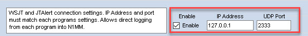
Note that for duplicate and multiplier information to be recorded and transferred correctly, the correct contest must be selected in N1MM+, and the program must be in Digital logging mode (e.g. by selecting a Digital button in the Band Panel or by typing PSK31 into the call sign box in the Entry window and pressing Enter). Note that the contest Mode category in the contest setup dialog window must contain DIGITAL. If the contest mode is RTTY, contacts in other modes (including FT8) will be assigned zero points. After changing RTTY to DIGITAL in the contest setup window to correct this, you will need to use the Tools > Rescore Current Contest menu item to rescore any FT8 QSOs that had not originally been assigned the correct score.
Within WSJT-X
Configure per the following settings on the >File >Settings page in the UDP Server and N1MM Logger + Broadcast panels:
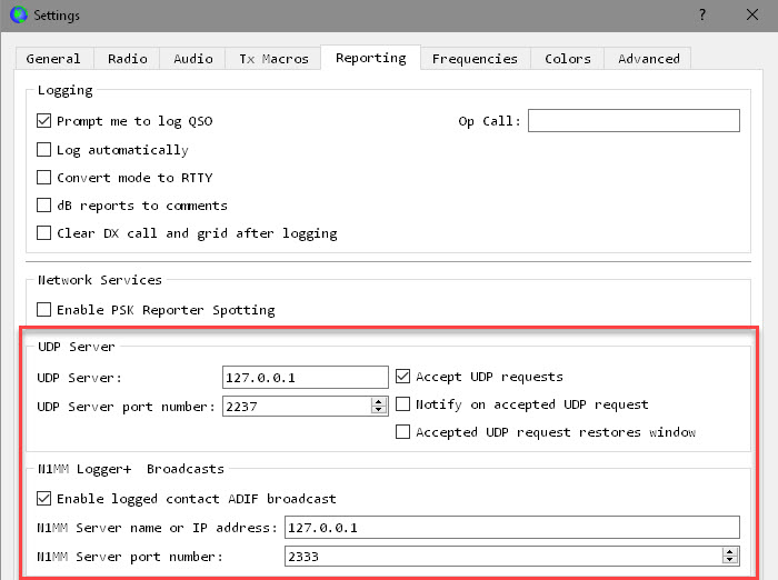
You only need to check the Accept UDP Requests checkbox on the right-hand side under UDP Server (see screenshot), plus the one check box on the left under N1MM Logger+ Broadcasts. The default port numbers are fine.
Configuration for a Specific Contests
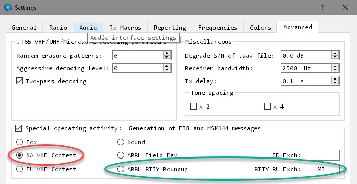
- If used during a contest, click the checkbox adjacent to the contest that you intend to operate
- For the ARRL RTTY Roundup – States and Provinces stations should insert their two character location abbreviation. DX stations should use the expression “DX”, which will enable sequential serial number exchanges.
- For the ARRL Field Day – Enter the section describing your station configuration (see ARRL instructions).
Launching WSJT-X Decode List
Open the WSJT-X Decode List from the N1MM+ >Windows >WSJT Decode List menu choice:
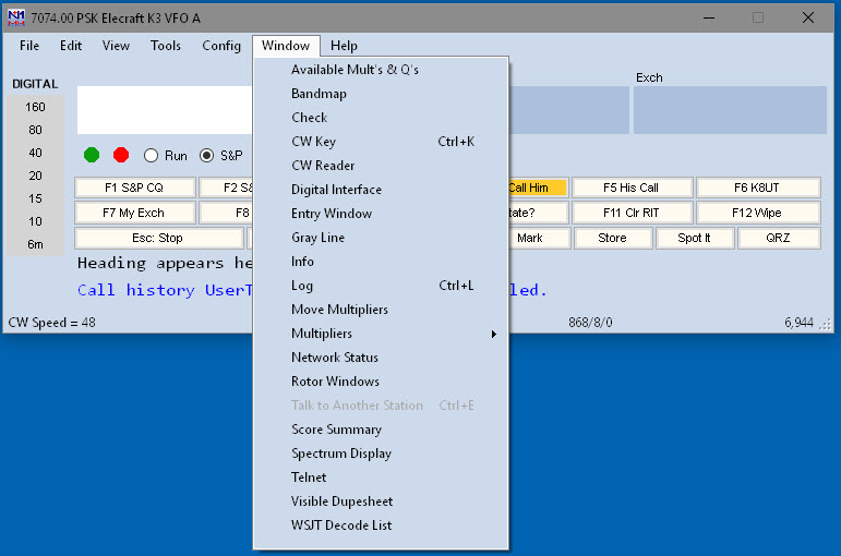
Opening this window will automatically initiate the UDP Server communications between WSJT-X and N1MM+ for the transfer of duplicate/worked/multiplier status from N1MM+ to WSJT-X. Once the window has been opened, do all of your operating from WSJT-X, and not from the N1MM Entry Window. In fact you can minimize (but do not close) the WSJT-X Decode List, and you can also minimize all of the N1MM+ windows temporarily if you want to to free up screen space.
Using WSJT-X Decode List
With the WSJT-X Decode List enabled, a list of up to 30 recent callsigns will be displayed with row colors indicating each callsign’s contest priority (grey for dupe or zero points, blue for workable but not a multiplier, red for new multipliers). Callsigns in the corresponding WSJT-X Band Activity panel will reflect those same contest color priorities as a background color. The only callsigns that are marked are callsigns of stations calling CQ. Callsigns of stations with QSOs in progress are not marked and do not appear in the WSJT Decode List.
To initiate a contact with a listed station, you may click on a callsign in either location (in the Logger’s WSJT Decode List window, or in the WSJT-X Band Activity window). Note that if you click on an “old” callsign, i.e. one that was sending CQ during the 15-second sequence before the most recent one, WSJT-X will not start transmitting until the correct time slot for calling that station (e.g. if the other station called CQ on an “even” time slot starting at 0 seconds or 30 seconds, WSJT-X will only call that station on an “odd” time slot starting at 15 seconds or 45 seconds).
When you click on a callsign, either in the WSJT Decode List window or in the WSJT-X Band Activity window, that call sign will also appear in the N1MM+ Entry window. This is for the purpose of doing a dupe/multiplier check; it is not part of the logging process. Do not enter the exchange into the Entry window. Simply complete the QSO in WSJT-X, up to and including the point where the QSO is logged in WSJT-X. After completing and logging a contact in WSJT-X, that contact will be logged in the WSJT-X ADIF log and the N1MM+ contest database simultaneously. At no point is there any need to type anything into any N1MM+ window; in fact, it is possible to operate in FT8 with all of the N1MM+ windows minimized to the Windows Task Bar and still have all of your FT8 QSOs recorded in the N1MM+ log. It is not necessary that the WSJT Decode List window in N1MM+ be visible; it can be minimized to the Task Bar and will still carry out its function of relaying dupe/multiplier status to WSJT-X.
When a callsign is listed in the WSJT-X DX Call field, the Decode List interface will persistently copy that callsign into the N1MM+ Entry Window callsign field (for example – the call will reappear after using <Wipe> to clear the N1MM+ Entry window). After you have completed a QSO in WSJT-X and it has been safely logged, you can use F4 in WSJT-X to clear the DX Call field while still running WSJT-X. This will clear the callsign field in the Entry window as well. If you are entering a contest that allows multiple modes, having WSJT-X put calls into the Entry window, or having it clear the Entry window, is definitely not something you want to have happen while you are using another mode. Therefore, you should always close the WSJT-X Decode List window and either shut down WSJT-X, or at least turn off decoding in WSJT-X, before changing to a non-WSJT mode.
WSJT-X Decode List FAQs
Rig Control – Can both WSJT-X and N1MM+ control the radio?
The only way that both programs can control the radio is if you are using a port splitter or virtual serial port application. If you do not have some kind of port splitting program to allow two programs to control the radio simultaneously, then plan on disabling rig control from N1MM+ and allowing WSJT-X to “drive” the radio settings whenever it is active. If you want to make contacts in RTTY, you will have to close WSJT-X or disable its rig control, re-enable rig control in N1MM+, and put N1MM+ into RTTY mode. Experimentation prior to the contest is highly recommended – see also FAQ #5.7 below.
There are a number of possibilities for port splitting. If your radio is one of those that supports one of these programs, one of the Win4K3Suite/Win4YaesuSuite/Win4IcomSuite programs may do what you need. N8LP’s LP-Bridge program is another possibility, although with at least one caveat — apparently, WSJT-X might only work with LP-Bridge’s Virtual Serial Port #1, i.e. the leftmost virtual port in the LP-Bridge window. Yet another option may be to use the DXLab Suite’s Commander program for rig control, configure WSJT-X to use Commander instead of controlling the rig directly, configure Commander’s “secondary CAT port” to lead and follow the primary port and use the Kenwood protocol, then configure N1MM+ to use the Kenwood protocol for radio control and connect it to Commander’s secondary CAT port via a connected virtual serial port pair (com0com). This is described in the DXLab Suite Wiki under “Interoperating with Software-Defined Radios”, substituting N1MM+ for the SDR software. Note that the only rig control functions supported by Commander’s secondary CAT port are frequency and mode control. CAT1ASC macros, RIT control, filter width commands and PTT via radio command from N1MM+ will not work using this method.
When using one of these methods, you may encounter problems with N1MM+ changing your radio mode from the setting required by WSJT-X for data versus the mode setting in N1MM+. Generally speaking, the radio mode you use for WSJT-X will be the same as the radio mode you would use for PSK. Therefore, if the “Mode sent to radio” is set up correctly under the Mode Control tab in the Configurer, then N1MM+ must be put into PSK mode (from the Entry window) whenever you are operating from WSJT-X. If you leave N1MM+ in RTTY mode (or CW or SSB), it may put the radio into the wrong mode (e.g. FSK or LSB for RTTY instead of USB or USB Digital for PSK/WSJT-X).
If you do share radio control using one of these methods, some of N1MM Logger+’s features may not work. The N1MM+ Development Team is unable to help with such situations, since the port splitting method used is outside our control. If you encounter problems with N1MM+ while using one of these methods, then before reporting a problem, please test to make sure you can reproduce the problem with no port splitting program active or involved. If you cannot reproduce the problem with no port splitting software in the picture, we are not likely to be able to resolve it.
No Rig Control – Does it work without rig control?
Yes. It is possible to use WSJT-X without rig control – but this requires some careful attention to detail when changing bands. You will need to change bands manually in both programs every time you change bands on the rig. Checking for duplicates and multipliers will not work correctly if the N1MM+ program is not set to the band you are operating on. Operating without rig control also means that some of WSJT-X’s features, notably the “Split” or “Fake It” techniques used to keep the sound card audio in the 1500-2000 Hz “sweet spot”, will not work.
Compatible with JTAlert – Can I run JTAlert at the same time?
No. The current versions of JTAlert and N1MM+ do not permit port sharing. You must close JTAlert for the WSJT-X Decode List to function. Furthermore, if you enable both the WSJT-X -to- N1MM+ logging interface and the JTAlert logging interface (without using the WSJT-X Decode List window in N1MM+), your contacts will be double-logged into the N1MM+ contest database.
Supported Contests – Does this only work with specific contests or can I use it with my general log?
You can use the WSJT-X Decode List with your general DX log or with any contest supported by WSJT-X.
For general logging, use WSJT-X in normal non-contest mode and use the DX log in N1MM+. Make sure the Mode category in the Contest Setup window for your DX log is set to SSB+CW+DIGITAL. If you leave it at the default SSB+CW, digital mode contacts made from WSJT-X may not be logged correctly, and the dupe checking will be wrong.
For contest logging, you will need to set the contest mode in WSJT-X under the Advanced tab in the Settings window. Check the check box called “Special operating activity” and then select the applicable contest and if necessary, fill in the contest exchange box. In N1MM+, open a contest log of the appropriate contest type, make sure the Mode category includes DIGITAL, and in the Entry window, put N1MM+ into Digital mode (e.g. by typing PSK31 into the call sign box and pressing Enter).
Callsign Colors – What do the callsign colors mean?
The callsign colors displayed by WSJT-X Decode List are derived from your N1MM+ settings found in the >Config >Manage Skins, Colors, and Fonts >Colors window under 3. Callsign Background Colors. By default those colors are:
- Grey = dupe or non-workable (zero-point contact)
- Blue = normal (new contact but not a new multiplier)
- Red = new multiplier
- Green = double multiplier (not applicable in contests supported by WSJT-X at this time, but may apply in future)
Serial Numbers – Will serial numbers from the two programs be in sequence?
In a word, no. If you make some contacts from N1MM+ (in RTTY, for example) and some contacts from WSJT-X (in FT8), the serial number sequences from the two programs will not be in sequence. There is no way for WSJT-X to know what serial numbers you have used in N1MM+, so it will issue its own serial numbers independently of what N1MM+ does. Don’t try to edit serial numbers to make the sequence look pretty – just accept whatever the two programs generate. What matters most is that your log reflects accurately what your software actually sent.
What do I need to do to switch between RTTY and FT8?
To go from RTTY (or other modes used in N1MM+) to FT8, first change the radio’s mode to the mode you use for FT8, and then (unless you have some kind of port sharing working) disable rig control in N1MM+ to allow WSJT-X to control the rig (in the Configurer, change the Radio column for the rig control port to None). Now start WSJT-X. Make sure the rig’s IF filtering is appropriate for FT8 (wide), and tune it to a frequency where contest FT8 QSOs are taking place (on the HF bands, the regular non-contest FT8 frequencies are not good places to try to make contest QSOs). Open the WSJT Decode List window in N1MM+. Note that while rig control is disabled in N1MM+, whenever you change bands in WSJT-X or on the radio, you also have to change bands in N1MM+ to ensure that the band in N1MM+ agrees with the band the radio is on, otherwise dupe and mult checking will be incorrect.
To go from FT8 to RTTY (or any other mode operated from N1MM+), first close the WSJT Decode List window. You may also wish to (or find it necessary to) minimize or shut down WSJT-X. If you receive a prompt from N1MM+ telling you it has detected that WSJT-X has shut down and asking whether you want to close, just answer No. If you do not have some kind of port sharing method active to allow both programs to control the rig at the same time, enable rig control in N1MM+ by setting the Radio listbox for the rig control port to your radio’s model. Make sure the rig is set to the correct mode with the appropriate filtering, and tune it to an appropriate frequency (presumably not the frequency you were using for FT8).
Note that if you leave WSJT-X running with the WSJT Decode List window active while you are trying to make RTTY contacts, WSJT-X will take control of the N1MM+ Entry window and you will be unable to log RTTY contacts. WSJT-X is persistent in sending the characters from its DX Call field into N1MM+’s Entry Window callsign field. Even if DX Call is empty (blank) it sends a blank to N1MM+ – wiping out anything you may try to enter in N1MM+. You must close the WSJT-X Decode List window and possibly the WSJT-X program as well when operating from N1MM+. Conversely, you must do all of your FT8 operating from WSJT-X. Do not try to enter anything into the N1MM+ Entry window while WSJT-X is active and the WSJT-X Decode List window is open.
Why are my FT8 contacts being scored with zero points?
If your FT8 contacts are being assigned zero points in the Log and Score Summary windows, it is likely that you have selected the wrong Mode category in the N1MM+ contest setup. Use the File > Open Log in Database… menu item to open the contest setup dialog window, and change the Mode category from RTTY to DIGITAL (ARRL RTTY contest), or from SSB+CW to SSB+CW+DIGITAL (VHF contests, general DX logging).
The logging interface into N1MM+ does not refresh the contest score when you change the contest category. Use the >Tools >Rescore Current Contest menu item to rescore previously-logged QSOs, and the score should be accurate thereafter (as long as you don’t change contest settings again).